FREE 1 to 3-Day Delivery on Orders $119+ Details
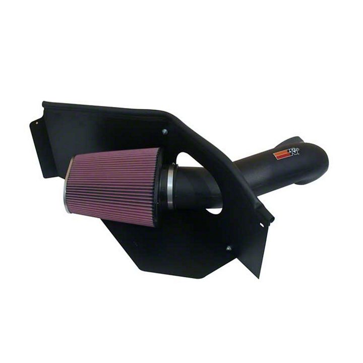
How to Install K&N Series 57 FIPK Cold Air Intake on your Ram
Installation Time
1 hours
Tools Required
- Flat Blade Screwdriver
- Ratchet
- Extension
- #27 torx socket
- 4mm Allen wrench
- 10mm Wrench
- 8mm Socket
- 10mm Socket
- 13mm Socket
- 9/16” Socket
Shop Parts in this Guide
NOTE: FAILURE TO FOLLOW INSTALLATION INSTRUCTIONS AND NOT USING THE PROVIDED HARDWARE MAY DAMAGE THE INTAKE TUBE, THROTTLE BODY AND ENGINE.
TO START:
1. Turn off the ignition and disconnect the negative battery cable.
NOTE: Disconnecting the negative battery cable erases pre-programmed electronic memories. Write down all memory settings before disconnecting the negative battery cable. Some radios will require an anti-theft code to be entered after the battery is reconnected. The anti-theft code is typically supplied with your owner’s manual. In the event your vehicles’ anti-theft code cannot be recovered, contact an authorized dealership to obtain your vehicles anti-theft code.
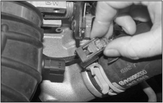
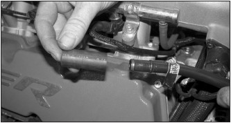
2. Depress the locking tab and then disconnect air temperature sensor electrical connection as shown.
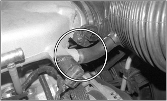
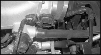
3. Remove the idle air hose from the idle air solenoid as shown.
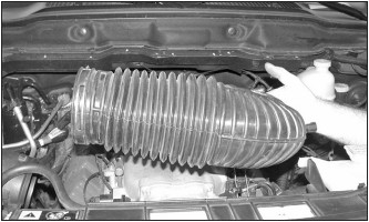
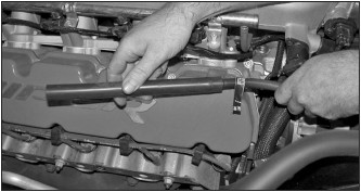
4. Loosen the two hose clamps that secure the intake tube to the throttle body and factory air box, and then remove the intake tube from the vehicle.
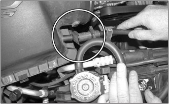
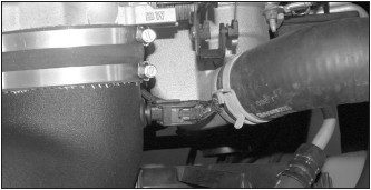
5. Loosen the crankcase vent tube clamp, and then disconnect the vent tube from the air box lid as shown.
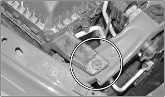
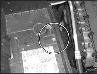
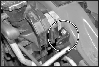
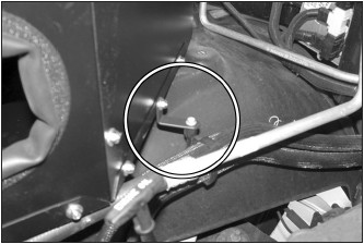
6. Remove the air box mounting nut shown.
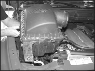
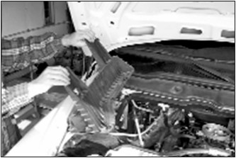
7. Remove the air box assembly from the vehicle as shown.
NOTE: K&N recommends that customers do not discard factory air intake.
8. Remove the heater hose bracket mounting bolt shown.
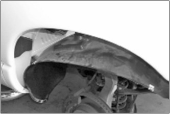
9. Remove the 8 bolts that retain the inner fender to the vehicle. To allow inner fender wall to drop for access to the lower airbox mount bolts.
NOTE: Not necessary to remove tire to access those bolts.
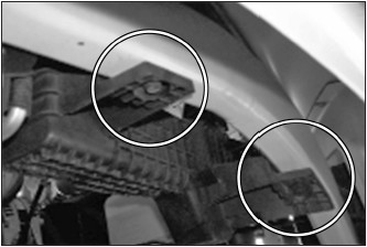
10. Use a 13mm wrench to remove the two bolts that retain the lower airbox mount.
11. Use a 13mm wrench to remove the two bolts that retain the upper airbox mount.
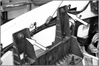
12. Remove the air box mount as shown.
13. Re-install the inner fender with the bolts that was removed in step 7.
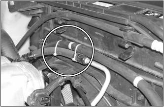
14. Unhook the A/C hose from the mounting clips on the radiator fan shroud as shown.

15. Using the tie-wraps provided, strap the A/C hose to the P/S hose as shown.
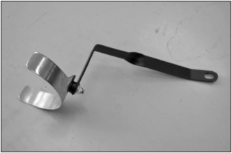
16. Assemble the saddle bracket assembly as shown.
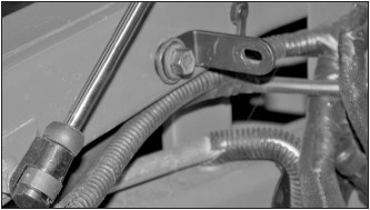
17. Remove the upper alternator mounting bolt as shown.
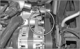
18. Install the saddle bracket assembly onto the alternator with bolt removed in step 17.
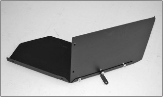
19. Install the heat shield side panel (074031) onto the heat shield base (074030) with the “L” bracket (07078) as shown with the provided hardware. NOTE: The L bracket should be installed at the center mounting location with the 16mm long bolt. Do not completely tighten the bolts at this time.
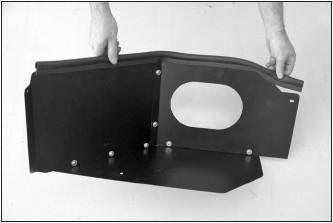
20. Install the heat shield side panel (074011) with the provided hardware as shown.

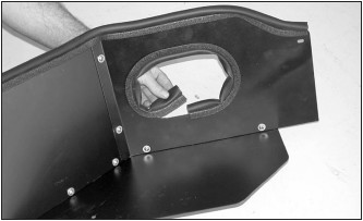
21. Install the provided edge trim onto the heat shield as shown.
NOTE: Some trimming of the edge trim may be necessary.
22. Install the provided edge trim into the hole in the heat shield as shown.
NOTE: Some trimming of the edge trim may be necessary.
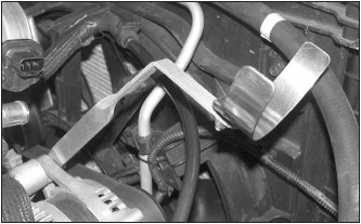
23. Install the “L” bracket (070066) onto the radiator core support with the provided hardware as shown.
24. Install the “L” bracket (070712) onto the inner fender with one of the bolts removed in step #11.
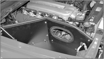
25. Install the heat shield assembly into the vehicle and secure to the mounting brackets installed in steps #23 and #24 with the provided hardware.
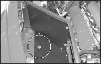
26. Install the heat shield mounting bolt through the base of the heat shield and through the inner fender well, secure with the provided nut.
NOTE: Be sure to use the two large fender washers, one on the top and one on the underside against the plastic inner fender.
27. Using the bolt removed in step #8, secure the heater hose-mounting bracket to the “L” bracket installed on the heat shield in step #19.
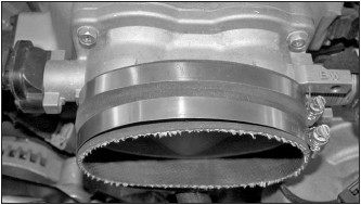
28. Install the silicone hose (08623) onto the throttle body and secure with the provided hose clamp as shown.
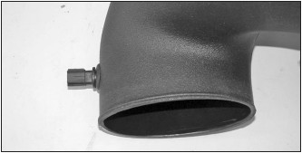
29. Install the provided silicone hose onto the idle air vent port as shown.
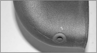
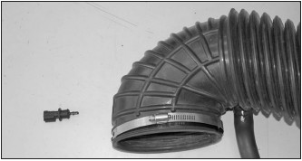
30. Install the provided grommet into the K&N® intake tube as shown.
31. Remove the air temperature sensor from the stock intake tube as shown.
32. Install the air temperature sensor into the grommet installed into the K&N® intake tube as shown.
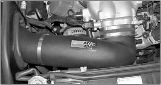
33. Install the K&N® intake tube into the silicone hose on the throttle body and onto the saddle clamp then secure with the provided hose clamps as shown.
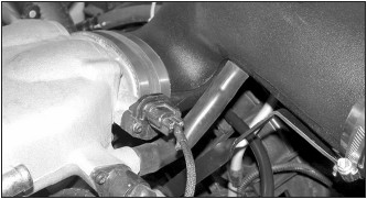
34. Install the idle air hose onto the K&N® intake tube as shown.
NOTE:Some trimming of the a silicone hose may be necessary to eliminate any kinks or binds.
35. Reconnect the air temperature electrical connection.
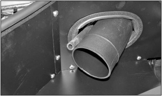
36. Remove the rubber coupling hose from the crank case vent tubing as shown.
37. Install the supplied silicone vent hose onto the factory crank case vent tubing as shown.
38. Pass the new crank case vent hose through the heat shield as shown.
39. Install the supplied hose mender into the K&N® air filter as shown.
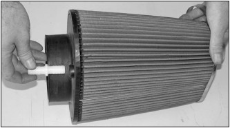
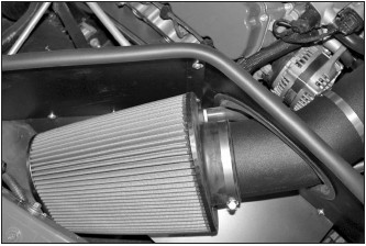
40. Install the K&N® air filter onto the K&N® intake tube as shown; the base of the filter flange should meet the 2nd bead on the intake tube. Line up the hose mender with the crankcase vent hose and then install the vent hose onto the hose mender. Secure the filter with the provided hose clamp.
NOTE: Rotate the filter on the intake tube to obtain minimum of 1/2” clearance of the filter material to the heat shield.
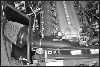
41. Reconnect the vehicle’s negative battery cable. Double check to make sure everything is tight and properly positioned before starting the vehicle.
42. The C.A.R.B. exemption sticker, (attached), must be visible under the hood so that an emissions inspector can see it when the vehicle is required to be tested for emissions. California requires testing every two years, other states may vary.
43. It will be necessary for all K&N® high flow intake systems to be checked periodically for realignment, clearance and tightening of all connections. Failure to follow the above instructions or proper maintenance may void warranty.
ROAD TESTING:
1. Start the engine with the transmission in neutral or park, and the parking brake engaged. Listen for air leaks or odd noises. For air leaks secure hoses and connections. For odd noises, find cause and repair before proceeding. This kit will function identically to the factory system except for being louder and much more responsive.
2. Test drive the vehicle. Listen for odd noises or rattles and fix as necessary.
3. If road test is fine, you can now enjoy the added power and performance from your kit.
4. K&N Engineering, Inc., requires cleaning the intake system’s air filter element every 100,000 miles. When used in dusty or off-road environments, our filters will require cleaning more often. We recommend that you visually inspect your filter once every 25,000 miles to determine if the screen is still visible. When the screen is no longer visible some place on the filter element, it is time to clean it. To clean and re-oil, purchase our filter Recharger® service kit, part number 99-5050 or 99-5000 and follow the easy instructions.