FREE 1 to 3-Day Delivery on Orders $119+ Details
How to Install ReadyLIFT 4 in. Front / 1.75 in. Rear SST Lift Kit on your Sierra
Shop Parts in this Guide
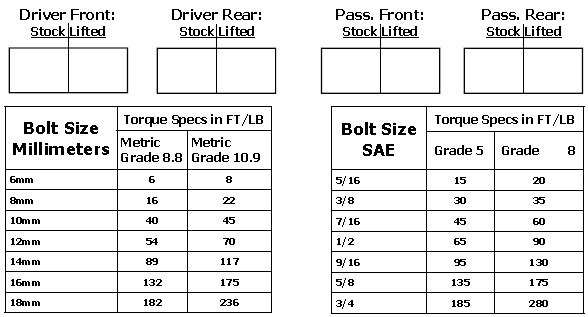
Vehicle ride height chart
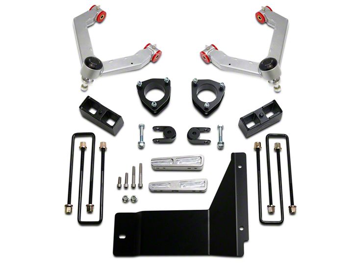
Bill of Materials
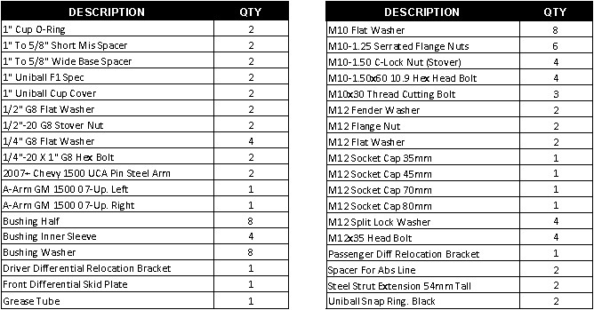
The Bill of Materials represents the component contents of this kit. All hardware is of the highest grade and the components are manufactured to exacting specifications for a trouble free installation. Use the attached torque specifications chart when final tightening of the nut and bolts are done.
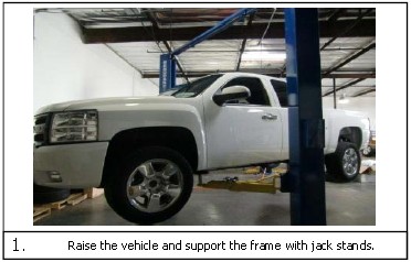
1. Raise the vehicle and support the frame with jack stands.
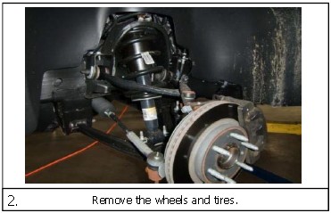
2. Remove the wheels and tires.
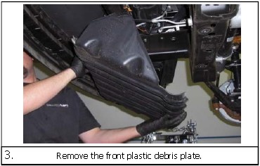
3. Remove the front plastic debris plate.
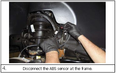
4. Disconnect the ABS sensor at the frame.
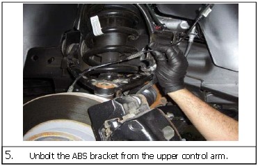
5. Unbolt the ABS bracket from the upper control arm.
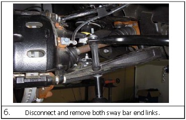
6. Disconnect and remove both sway bar end links.
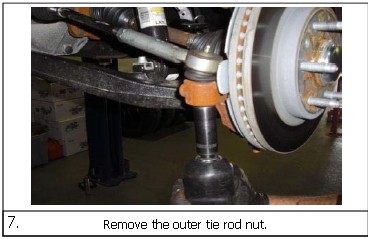
7. Remove the outer tie rod nut.
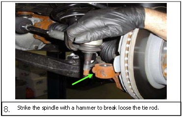
8. Strike the spindle with a hammer to break loose the tie rod.
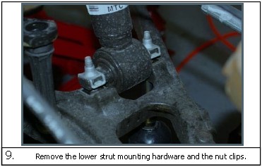
9. Remove the lower strut mounting hardware and the nut clips.
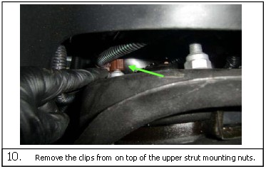
10. Remove the clips from on top of the upper strut mounting nuts.
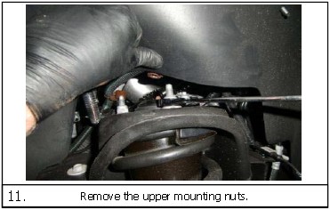
11. Remove the upper mounting nuts.
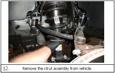
12. Remove the strut assembly from vehicle.
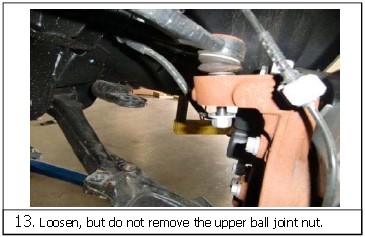
13. Loosen, but do not remove the upper ball joint nut.
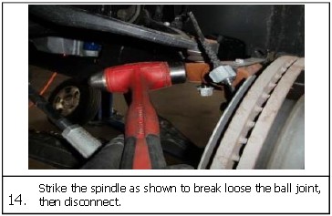
14. Strike the spindle as shown to break loose the ball joint, then disconnect.
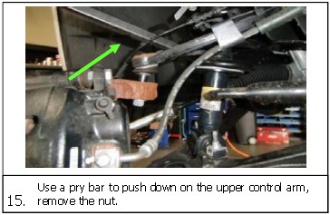
15. Use a pry bar to push down on the upper control arm, remove the nut.
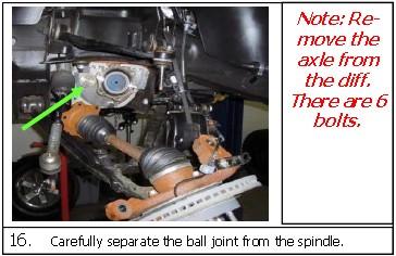
16. Carefully separate the ball joint from the spindle.
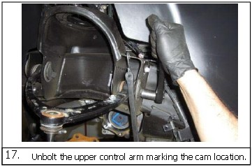
17. Unbolt the upper control arm marking the cam location.
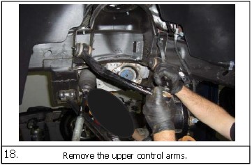
18. Remove the upper control arms.
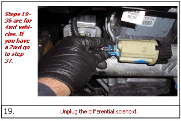
19. Unplug the differential solenoid.
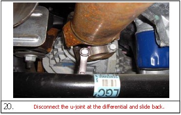
20. Disconnect the u-joint at the differential and slide back.
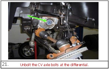
21. Unbolt the CV axle bolts at the differential.
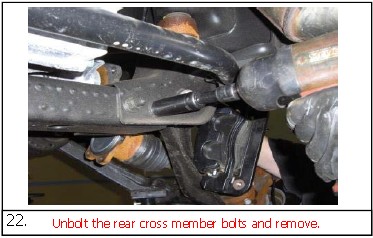
22. Unbolt the rear cross member bolts and remove.
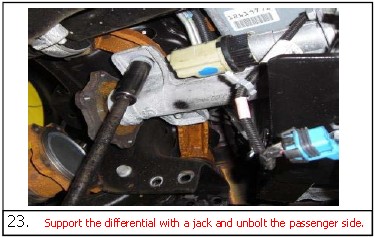
23. Support the differential with a jack and unbolt the passenger side.
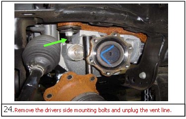
24. Remove the drivers side mounting bolts and unplug the vent line.
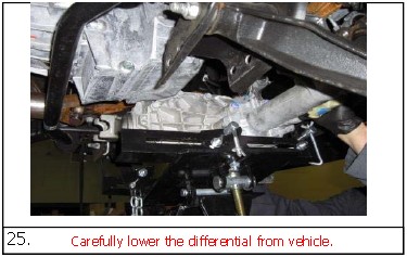
25. Carefully lower the differential from vehicle.
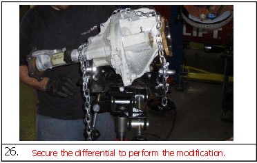
26. Secure the differential to perform the modification.
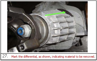
27. Mark the differential, as shown, indicating material to be removed.
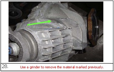
28. Use a grinder to remove the material marked previously.
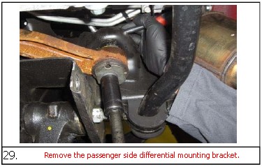
29. Remove the passenger side differential mounting bracket.
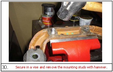
30. Secure in a vise and remove the mounting studs with hammer.
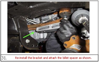
31. Re-install the bracket and attach the billet spacer as shown.
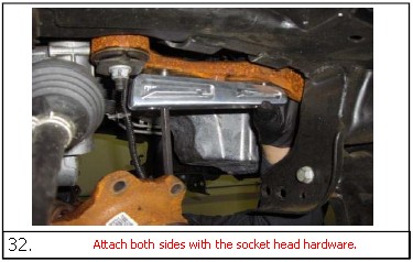
32. Attach both sides with the socket head hardware.
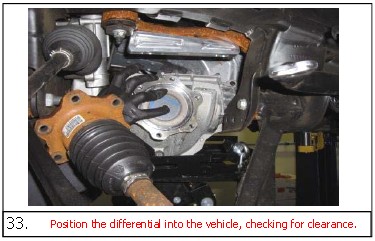
33. Position the differential into the vehicle, checking for clearance.
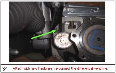
34. Attach with new hardware, re-connect the differential vent line.
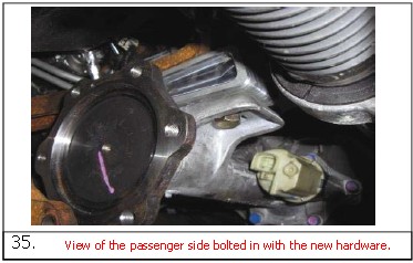
35. View of the passenger side bolted in with the new hardware.
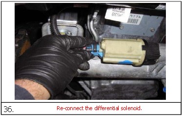
36. Re-connect the differential solenoid.
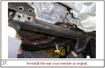
37. Re-install the rear cross member as original.
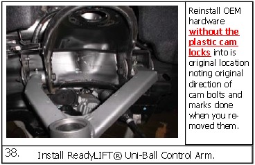
38. Install ReadyLIFT® Uni-Ball Control Arm.
Reinstall OEM hardware without the plastic cam locks into is original location noting original direction of cam bolts and marks done when you re-moved them.
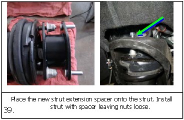
39. Place the new strut extension spacer onto the strut. Install strut with spacer leaving nuts loose.
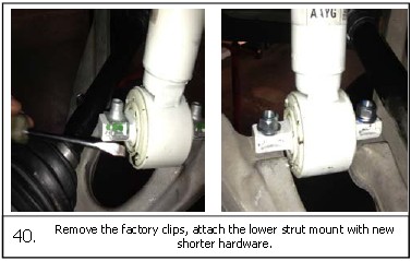
40. Remove the factory clips, attach the lower strut mount with new shorter hardware.
41. When attaching strut to vehicle be sure to use provided hardware. The serrated flange nuts go on top and the self locking nuts with washers go on bottom with grade 8 bolts.
The OEM lower nut clips and bolts will not be used. Doing so will cause damage to you vehicle.
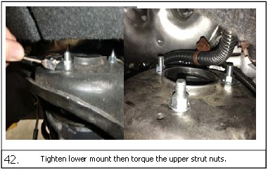
42. Tighten lower mount then torque the upper strut nuts.
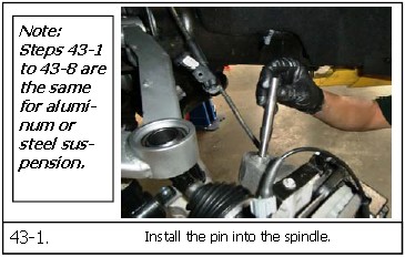
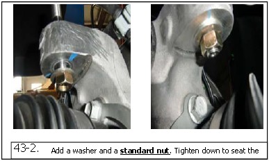
43-1. Install the pin into the spindle.
43-2. Add a washer and a standard nut. Tighten down to seat the
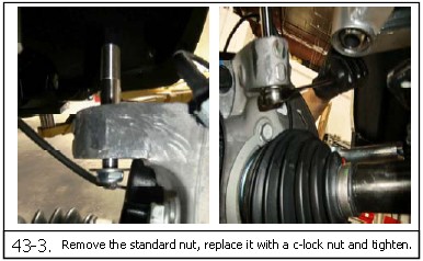
43-3. Remove the standard nut, replace it with a c-lock nut and tighten.
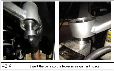
43-4. Insert the pin into the lower misalignment spacer.
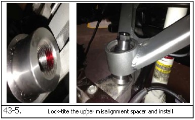
43-5. Lock-tite the upper misalignment spacer and install.
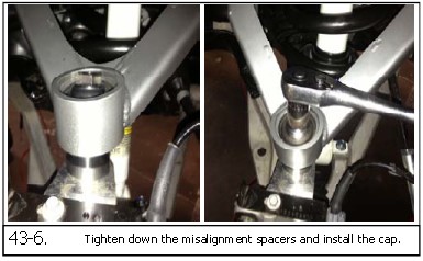
43-6. Tighten down the misalignment spacers and install the cap.
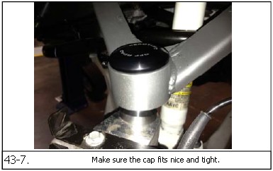
43-7. Make sure the cap fits nice and tight.
43-8. You may need to put a small amount of grease on the o-ring of the cap to help pre-vent the o-ring from rolling and binding up. A trick also is to twist the cap while applying pressure to achieve a nice and snug fit.
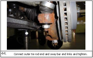
44. Connect outer tie rod end and sway bar end links and tighten.
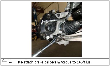
44-1. Re-attach brake calipers & torque to 145ft lbs.
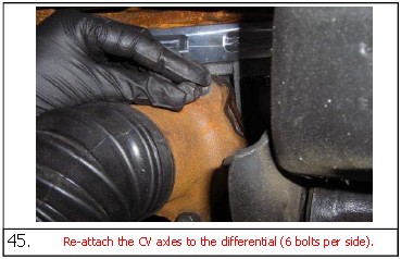
45. Re-attach the CV axles to the differential (6 bolts per side).
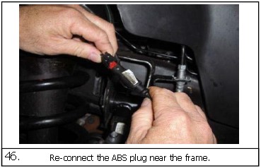
46. Re-connect the ABS plug near the frame.
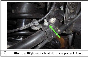
47. Attach the ABS/brake line bracket to the upper control arm.
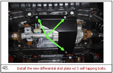
48. Install the new differential skid plate w/ 3 self tapping bolts.
49. Note: The following installation instructions cover both the 2/4WD 1500 pick-ups. This kit will work on vehicles with AutoRide, NOT AutoLeveling, unless you are willing to make modifications. ReadyLIFT® does not supply parts and or methods to accommodate vehi-cles with this option.
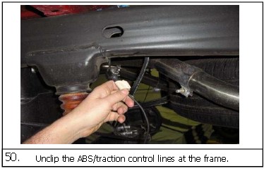
50. Unclip the ABS/traction control lines at the frame.
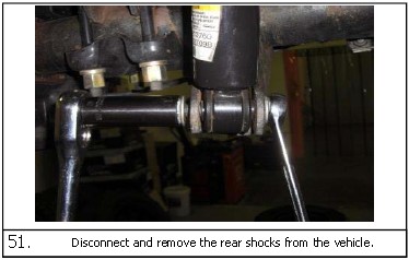
51. Disconnect and remove the rear shocks from the vehicle.
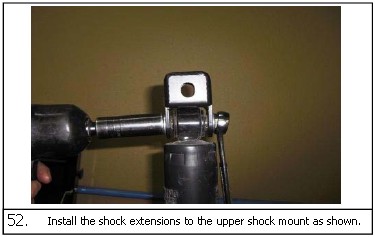
52. Install the shock extensions to the upper shock mount as shown.
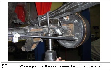
53. While supporting the axle, remove the u-bolts from axle.
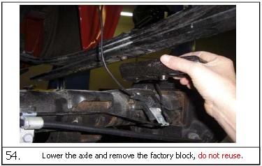
54. Lower the axle and remove the factory block, do not reuse.
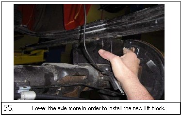
55. Lower the axle more in order to install the new lift block.
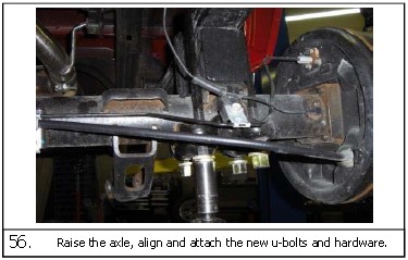
56. Raise the axle, align and attach the new u-bolts and hardware.
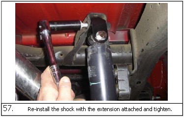
57. Re-install the shock with the extension attached and tighten.
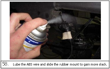
58. Lube the ABS wire and slide the rubber mount to gain more slack.
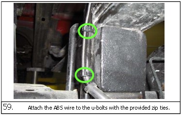
59. Attach the ABS wire to the u-bolts with the provided zip ties.
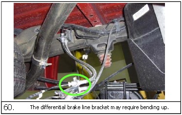
60. The differential brake line bracket may require bending up.
By installing this part you are accepting full responsibility and liability for proper wheel and tire fitment after installation.
It is the installer’s responsibility to properly align the vehicle before use. Using a wheel tire fitment combination that results in any contact from the tire and/or wheels with the new installed ReadyLIFT® upper control arm or inner fenders at any point including full steering lock will void the Ready-LIFT® warranty and may result in failure of the ball joints. Failure to do so may cause damage to your vehicle and/or injury or death to the driver and passengers.
Final Checks & Adjustments
Post Installation Warnings: Once the vehicle is lowered to the ground, check all parts which have rubber or urethane components to insure proper torque. Torque wheels to factory specs. Move vehicle backwards and forwards a short distance to allow suspension components to adjust. Turn the front wheels completely left then right and verify adequate tire, wheel, brake line, and ABS wire clearance. Test and inspect steering, brake and suspension components for tightness and proper operation. In-spect brakes hoses and ABS lines for adequate slack at full extension. Failure to perform the post in-spection checks may result in vehicle component damage and/or personal injury or death to driver and/ or passengers and void your warranty. Test drive vehicle and re-check the torque of all fasteners and re-torque wheels on vehicle.
Wheel Alignment/Headlamp Adjustment:
It is mandatory to have a proper and professional wheel alignment performed by a certified alignment technician. Align the vehicle to factory specifications. It is mandatory that your vehicle alignment be checked after any off-road driving. In addition to your vehicle alignment, for your safety and others, it is necessary to check and adjust your vehicle headlamps for proper aim and alignment.
Vehicle Re-Torque and Safety Inspection:
Upon completion of all services and adjustments performed on your vehicle, and within 50 miles of driv-ing, check to ensure all fasteners and hardware are properly torqued to specification as noted in the vehicles factory service manual or the torque chart included.