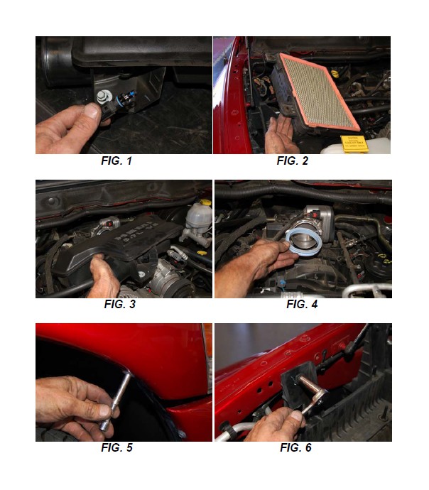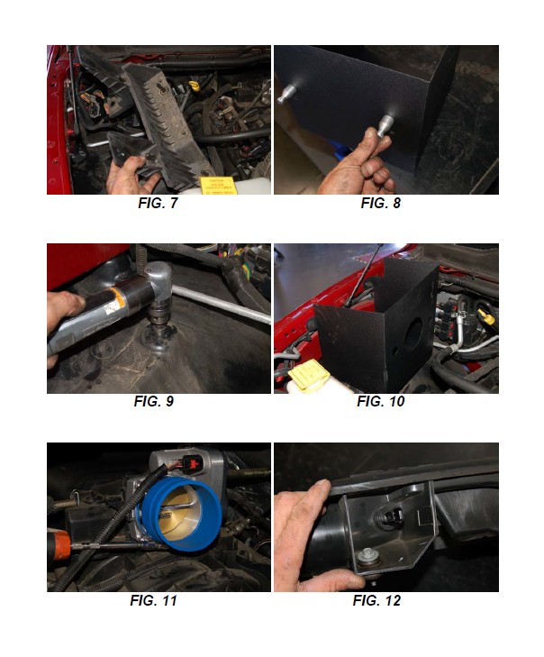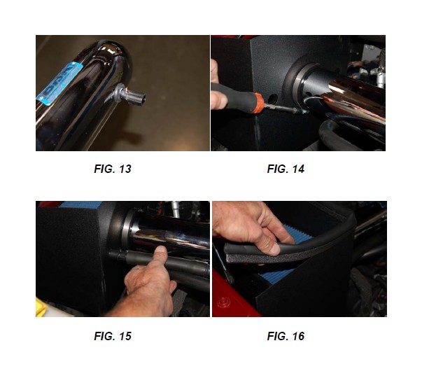
How to Install BBK Chrome Cold Air Intake on your Ram
Installation Time
1 hours
Tools Required
- 8,10, 13mm sockets
- ratchet
- Philipshead screwdriver
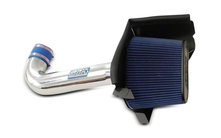
Shop Parts in this Guide
STEP 1: Disconnect the negative battery terminal.
STEP 2: Unplug Intake Air Temp Sensor. Its located in the front of the decorative plenum box, just to the right of the inlet hose connection. Turn sensor to the left to unlock and remove. FIG. 1
STEP 3: Loosen the hose clamp on the inlet hose where it connects to the decorative plenum. Release clamps on airbox lid and remove lid and inlet hose. Remove airbox bottom and Filter. FIG. 2
STEP 4: Loosen the two bolts that hold the plenum to the intake manifold. Remove plenum. Remove rubber seal from throttle body. FIGS. 3 and 4
STEP 5: Remove the seven (7) inner fender screws from under the fender. FIG. 5
STEP 6: At the top of the fender opening, separate the plastic inner fender from the steel outer Fender and feel inside for the two (2) bolts that hold the bottom of the air box mount. Remove the two bolts. Remove the two that hold the bracket to the fender in the engine Compartment. Remove the bracket. FIG. 6 and 7
STEP 7: Reinstall inner fender and all seven screws.
STEP 8: Install the supplied aluminum pins to the bottom of the air shield using the supplied screws. FIG. 8
STEP 9: Earlier model pickups have rubber grommets on the bottom of the stock air box. Remove And install on these aluminum pins. Later model pickups have screws that held the air box Mounting bracket to the inner fender. If yours has the screws, then drill out the screw holes In the plastic inner fender to 9/16”. Then the aluminum pins will locate in the holes. FIG. 9
STEP 10: Install the BBK air filter shield inplace on inner fender. Secure with the stock (2) bolts. FIG. 10
STEP 11: Install the supplied blue rubber hose coupler onto the throttle body. Install the clamps and Tighten the one on the throttle body. FIG. 11
STEP 12: Install the supplied black rubber grommet in the chrome inlet tube. Install the Intake Air Temp (IAT) sensor that you removed from the stock plenum in STEP 2, into the grommet. FIG. 12 and 13
STEP 13: Install the chrome inlet tube into the filter shield then onto the blue hose connector on the throttle body. Tighten clamp. Connect IAT sensor plug.
STEP 14: Take the clamp off the neck of the supplied air filter and place on chrome inlet tube, on the engine side of the shield. Install the filter onto the tube and line up the breather hole in the filter base with the forward hole in the shield. Place clamp on neck of filter and tighten. FIG. 14
STEP 15: Insert the supplied 5/8” black plastic hose connector into the hole in the base of the filter, connect the stock breather hose to the black connector. If you need a little extra length In the breather hose, loosen the clamp at the other end of the hose, where it connects to the engine and turn the hose toward the air filter. FIG. 15
STEP 16: Install sponge seal to top of air filter shield. Trim off extra. FIG. 16
STEP 17: Reconnect the negative battery terminal.
