How to Install Baer Extreme Plus Rear Brake Kit - Black (07-18 Sierra 1500) on your GMC Sierra
Shop Parts in this Guide
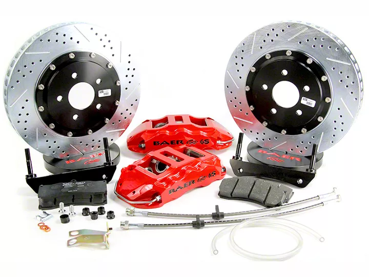
- Baer Extreme+ Rear Big Brake Kit with 15-Inch Rotors; Black Calipers (99-25 Sierra 1500 w/ Rear Disc Brakes)
- Baer Extreme+ Rear Big Brake Kit with 15-Inch Rotors; Silver Calipers (99-25 Sierra 1500 w/ Rear Disc Brakes)
- Baer Extreme+ Rear Big Brake Kit with 15-Inch Rotors; Red Calipers (99-25 Sierra 1500 w/ Rear Disc Brakes)
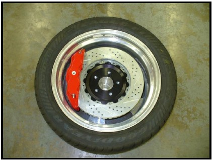
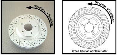
When installing new Baer rotors, be sure to follow the direction of rotation indicated on the rotor hat area with either an arrow, or an “L” for left, or an “R” for right, or both. “L” or left always indicates the driver’s side of US spec vehicles. Images shown are “L” left rotors:
INSTALLATION:
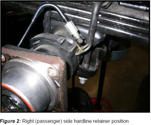
6. Carefully bend the factory hardlines forward and down, as shown in Figure 2. Once completed, install the clamp and hose bracket from the hardline retainer assembly. Figure 2 depicts this process.
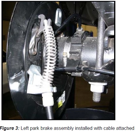
7. Install the new park brake assemblies using the original brake backing plate bolts and torque each bolt to 85 ft∙lbs. Both park brake assemblies are identical. The left (driver’s side) caliper will mount in the “leading” (towards the front of the vehicle) position with the park actuator at the rear of the vehicle. The passenger side will mount similarly. Figure 3 displays the installation of the driver side park brake assembly.
For vehicles with factory disc brakes, follow steps 9A-14:
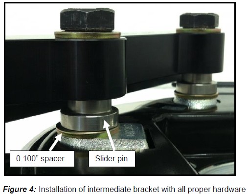
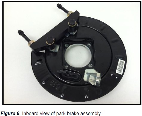
10. Install the new intermediate bracket to the original caliper mount located on the inboard side of the flange housing using the supplied M14-2.0x60 bolts, washers, spacers, and slider pins (bracket part number faces inboard). **Note: Due to system requirements and fitment, the use of 0.100” thickness spacers will be required. The spacers will rest between the flange housing and the head of the slider pin. Add extra shims as needed to center the caliper. Ensure that the dust shield does not interfere with the bracket in any way. Slide the bracket inboard followed by sliding it outboard, along the slider pins. Remove material from the dust shield if interference occurs. Tighten the bolts for now as shimming will need to occur.
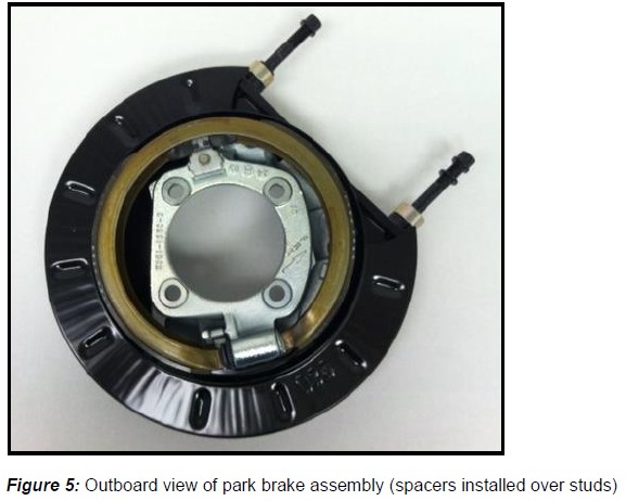
Note: The intermediate bracket will arrive pre-installed to the caliper for ease of shipping. Also, the M14-2.0x60 bolts, washers, and slider pins will come attached with this assembly, too. See Figures 4-6 for reference of install.
11. The next step is to slide the spacers over the radial mount studs and onto the intermediate bracket. For Extreme 15” brake systems, 0.500” thick spacers are supplied (one per radial stud).
Shimming Procedure
For vehicles with factory drum brakes, follow step 13A
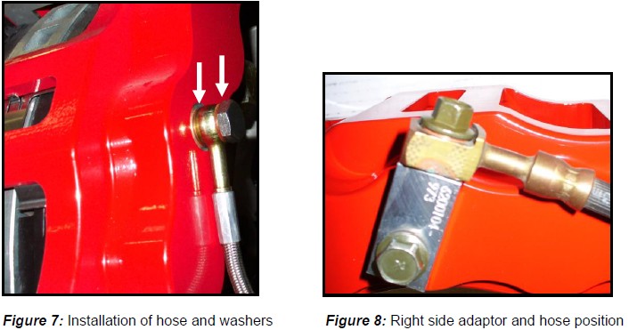
13A. Finger tighten the steel braid banjo hose end with one copper washer on each side of the banjo fitting into the rear of the caliper. Connect the hose to the hardline at the frame and install the hose lock. **IMPORTANT: Position the hose to avoid interference with the wheel and suspension components through the entire range of motion. Tighten fitting and banjo bolt to 15-20 ft∙lbs. See Figure 7 for reference, shown below.
For vehicles with factory disc brakes, follow step 13B
13B. This system will use the original hoses to supply fluid. New copper washers are provided as these are a one-time use item. An adaptor block is also provided to attach to the caliper. The original hose and new banjo bolts will attach to this block. Position the adaptor block on the caliper as in Figure 8, and secure with the supplied short banjo bolt and two copper washers. Your original hose will attach to the adaptor block with the supplied long banjo bolt and two copper washers. The copper washers go on each side of the banjo fitting of the original hose. Torque both bolts between 15-20 ft∙lbs. **IMPORTANT: Ensure to route the brake hose away from suspension and wheels to avoid any interference through full articulation of suspension system. See Figure 8 below, for correct orientation.
14. Repeat these steps for the other side of the vehicle and be sure to recheck all attachment points and fittings.
