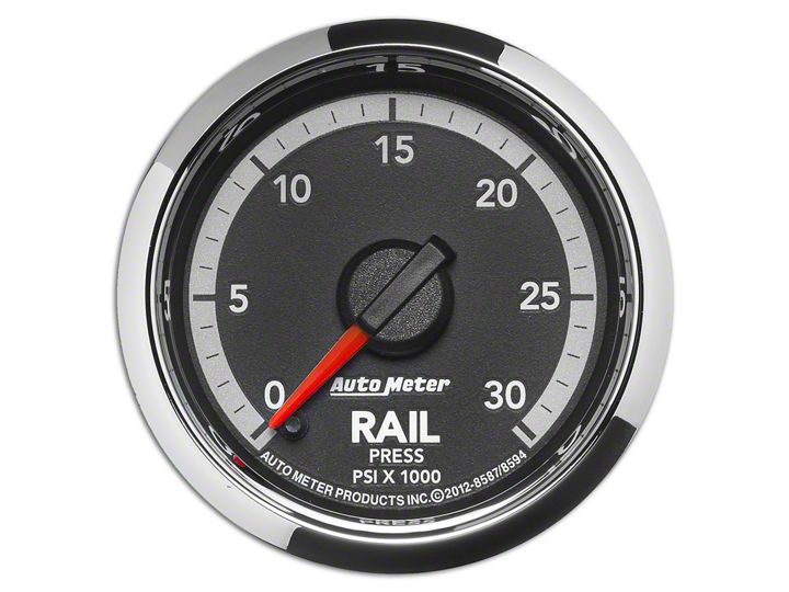
How to Install Auto Meter Fuel Rail Pressure Gauge - 0-30K PSI Digital Stepper Motor (09-17 RAM 1500) on your Dodge RAM
Shop Parts in this Guide
NOTE: When the ignition is off the pointer may not always rest at zero.
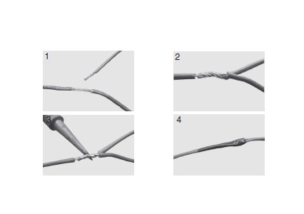
Recommended Splice
1. Carefully strip approximately 1/2" of the insulation from the OEM wire. Use caution not to cut or break wire while removing the insulation. (see figure 1.)
2. Wrap the bare end of the gauge harness wire around the bare OEM wire. (see figure 2)
3. Solder connection. (see figure 3)
4. Wrap splice with electrical tape to seal and insulate connection. (see figure 4)
Installation
1. Check that you have all parts required for installation, and the engine is cool.
2. Disconnect the negative (-) battery cable.
3. Gauge mounts in a 2-1⁄16” hole for 2-1⁄16” gauge. Use supplied brackets and nuts to secure gauge to dash or panel, if a friction fit or a pod mounted bracket are not used.
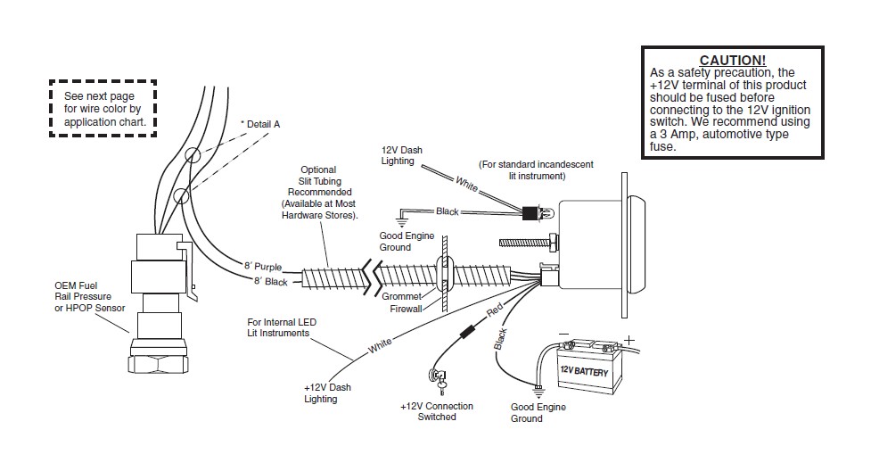
4. Drill 1” diameter hole where wires pass through sheet metal (such as firewall) and install rubber grommet provided. (Grommet will require slit). Route the necessary wire through the grommet into the engine compartment. The 8’ Purple and 8’ Black wires will need to be routed to the engine compartment.
5. Connect the white wire to dash lighting or switchable 12v light source, the 4’ red wire to a switched 12V source and the 4’ black wire to ground (see diagram for details).
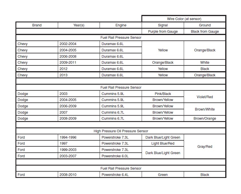
6. From the table below, determine the wire colors used in your vehicle for the signal and ground wires.
7. Locate the harness connected to the sensor (Fuel Rail Pressure or HPOP) in your vehicle. Confirm the harness matches the wires identified in the table.
8. Connect the 8’ Purple wire from the gauge harness to the signal wire.
9. Connect the 8’ Black wire from the gauge harness to the sensor ground.
10. Secure all wiring with cable ties (not included) to ensure they are kept away from moving parts, sharp edges, and high heat sources.
11. Reconnect negative (-) battery cable.
For example: The 2004 Dodge with a Cummins 5.9L uses a BROWN/YELLOW wire for Signal and a VIOLET/RED wire for Ground. The BROWN/YELLOW wire needs to be connected to the 8’ PURPLE wire from the gauge harness, and the VIOLET/RED wire needs to be connected to the 8’ BLACK wire from the gauge harness.
NOTE: It is recommended that the electrical connections made in the engine compartment be soldered, and wrapped with several layers of a good electrical tape.
CAUTION: If you will be working with the fuel system, take care to insure no sparks or flames occur.
Power-Up
The pointer will move backward to the stop pin and then move to the zero box, or current pressure reading. This procedure is an auto-calibration function and is performed on every power-up. While this test is being performed, the gauge may make a clicking sound. This is normal.
SERVICE
For service send your product to Auto Meter in a well packed shipping carton. Please include a note explaining what the problem is along with your phone number. Please specify when you need the product back. If you are sending product back for Warranty adjustment, you must include a copy (or original) of your sales receipt from the place of purchase.
