How to Install AFE Momentum GT Pro DRY S Cold Air Intake - Black on your Ram
Installation Time
1 hours
Tools Required
- 1/4" ratchet
- 10mm deep socket
- 8mm or 5/16" driver
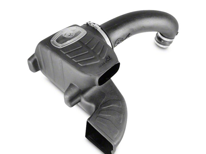
Shop Parts in this Guide
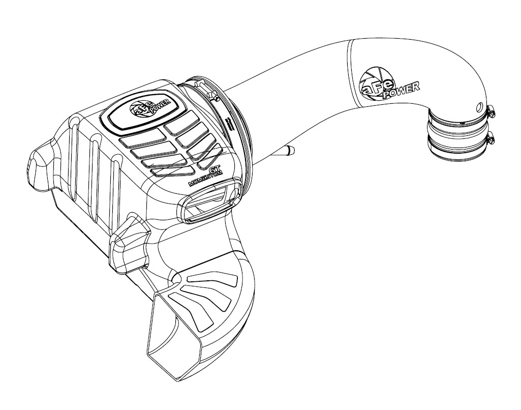
• Please read the entire instruction manual before proceeding.
• Ensure all components listed are present.
• If you are missing any of the components, call customer support at 951-493-7100.
• Ensure you have all necessary tools before proceeding.
• Do not attempt to work on your vehicle when the engine is hot.
• Disconnect the negative battery terminal before proceeding.
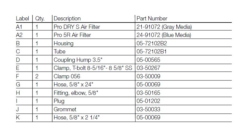

Refer to Figure A for steps 1-3
Step 1: Disconnect temperature sensor harness 1 .
Step 2: Remove and save temperature sensor using a ¼ turn counter-clockwise twist. Do not damage.
Step 3: Loosen the inlet tube clamps and remove tube.
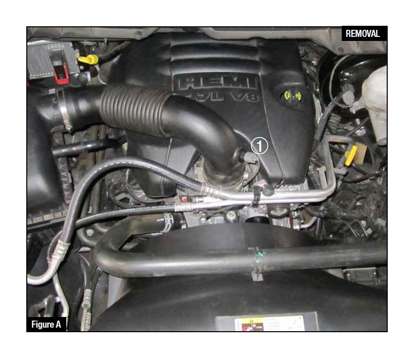
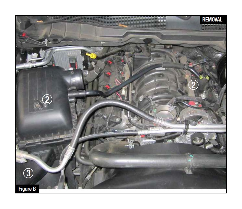
Refer to Figure B for steps 4-6
Step 4: Remove Engine cover.
Step 5: Remove vent tube from air box and engine vent 2 .
Step 6: Lift air box up and rotate towards the front for the scoop to clear the air condition lines 3 .
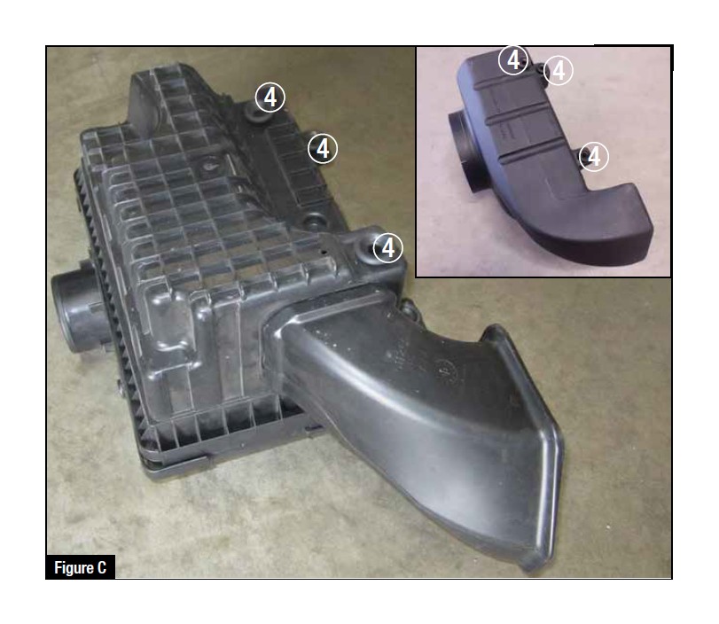
Refer to Figure C for step 7
Step 7: Transfer 3 of the rubber mounting grommets from the OE air box to the aFe filter housing as shown 4 .
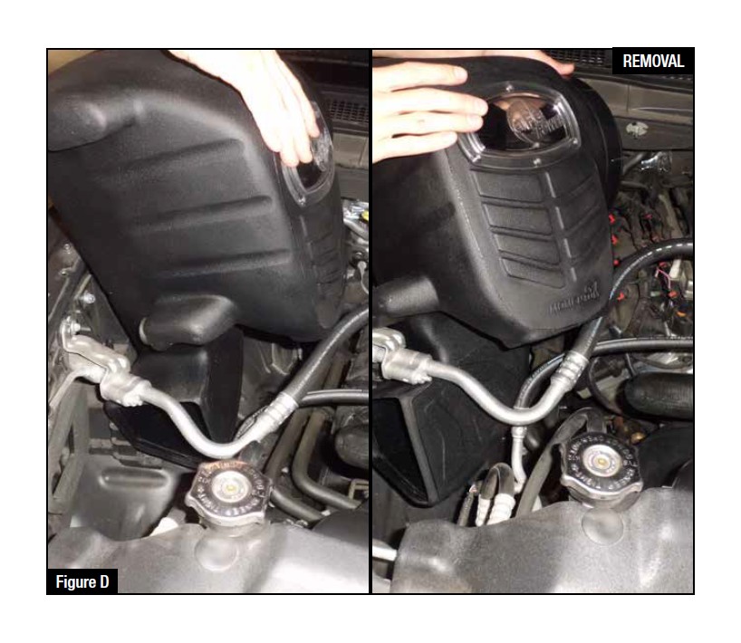
Refer to Figure D for steps 8-10
Step 8: Start housing installation as shown in the left picture.
Step 9: Lower the aFe filter housing into position with the scoop pointed downward and rotate to clear the air condition lines.
Step 10: Slip over the mounting pegs and firmly press down to seat housing.
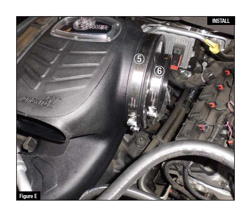
Refer to Figure E for steps 11-13
Step 11: Install large T-bolt clamp on aFe Momentum housing as shown 5 .
Step 12: Install air filter into housing as shown and tighten large T-bolt clamp.
Step 13: Slide smaller T-bolt clamp over filter flange as shown but do not tighten at this time 6 .
Refer to Figure G for step 14
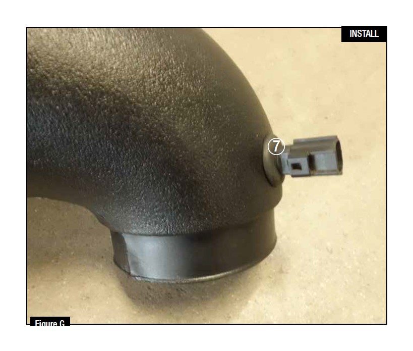
Step 14: Install the provided sensor grommet into the aFe inlet tube and carefully push in the sensor 7 .
Note: It may help to apply a small amount of lubricant to the inside of the rubber grommet.
Refer to Figure H for step 15
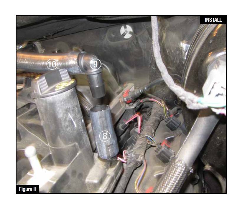
Step 15: Install the provided 5/8 x 2 1/4 hose 8 , 5/8 elbow 9 , and 5/8 x 24" hose 10 onto the engine vent fitting.
Note: Use a lubricant on both ends of elbow.
Refer to Figure I for steps 16-17
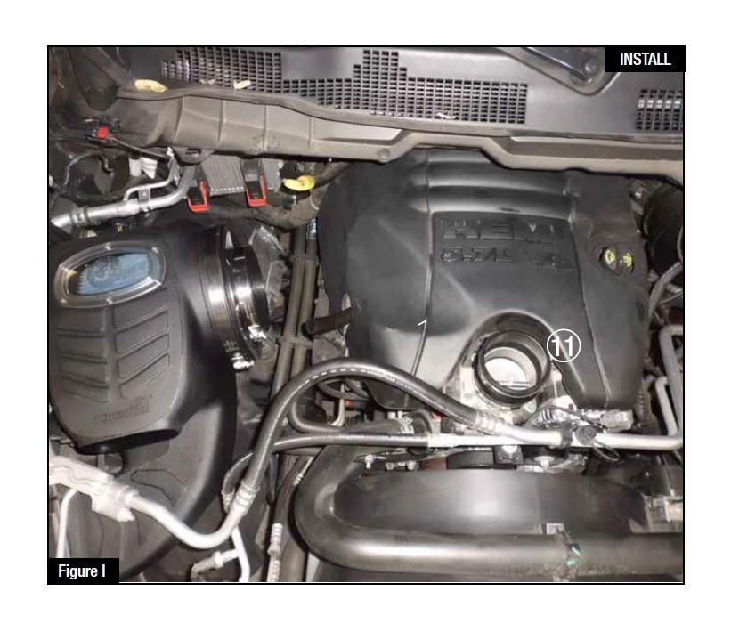
Step 16: Reinstall engine cover.
Step 17: Place hump coupler and (2) #056 clamps onto throttle body, do not tighten at this time 11 .
Refer to Figure J for steps 19-21
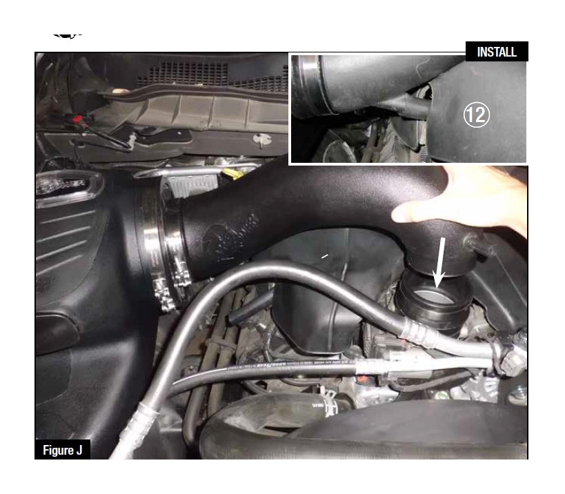
Step 19: Install aFe intake tube in filter first then insert smaller tube end into 3-1/2" coupling.
Step 20: Connect vent hose by reaching under engine cover and pushing onto tube vent 12 .
Step 21: Tighten all clamps.
Note: Use a lubricant on outside of tube vent.
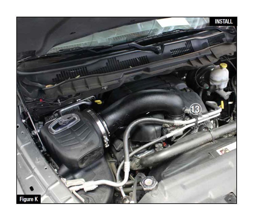
Refer to Figure K for step 22
Step 22: Reconnect temperature sensor harness 13 .
*Your installation is now complete.
Note: Retighten all connections after approximately 100-200 miles.
