
How to Install Zone Offroad 4 in. Suspension Lift Kit w/ Shocks on your F-150
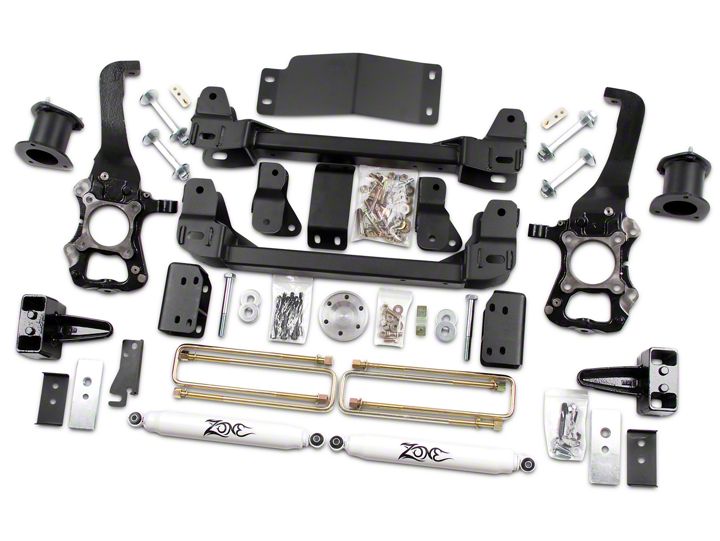
Shop Parts in this Guide
»Front Installation
1. Park the vehicle on a clean, flat surface and block the rear wheels for safety.
2. Measure from the center of the wheel up to the bottom edge of the wheel opening
and record below:
LF____________ RF____________
LR____________ RR____________
3. Raise the front of the vehicle and support with jack stands at each frame rail
behind the lower control arms.
4. Remove the front wheels.
5. Models equpped with Electronic Power Assist Steering - disconnect the power
steering control module connector to avoid arching of the contacts in the internal
power relay from a hammer blow or impact wrench.
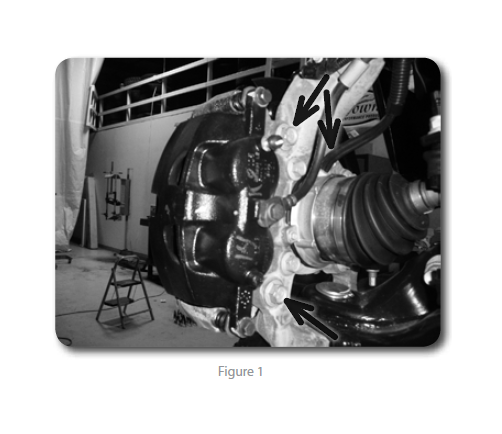
6. Remove the brake caliper anchor bracket bolts and remove the caliper from the
knuckle Figure 1. Hang the caliper out of the way. Do not let the caliper hang by
the brake hoses.
7. Disconnect the hub vacuum line from the hub. Figure 1
8. Remove the brake rotor and set aside.
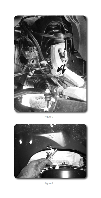
9. Disconnect the ABS and hub vacuum lines from the retaining clips. Disconnect
the brakeline bracket from the frame rail. Disconnect the ABS line from the inner
fenderwell, and disconnect the clip Figures 2 / 3.
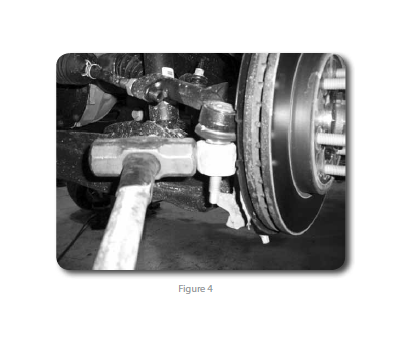
10. Disconnect the tie rod ends from the steering knuckles Figure 4. Remove and
retain the mounting nuts. Strike the steering knuckle near the tie rod end to dislodge
the end. Take care not to strike the tie rod end.
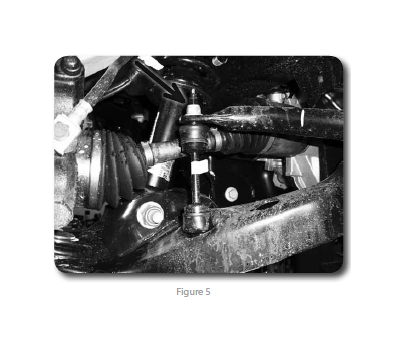
11. Disconnect the sway bar links from the sway bar Figure 5. Retain hardware. The
sway bar links do not need to be removed from the lower control arms.
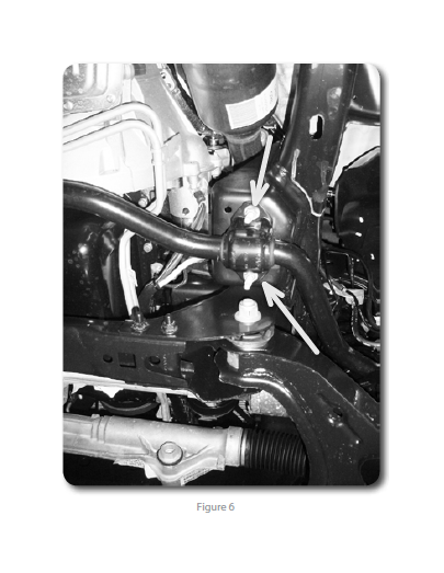
12. Remove the four sway bar mounting nuts and remove the sway bar from the
vehicle Figure 6. Retain hardware.
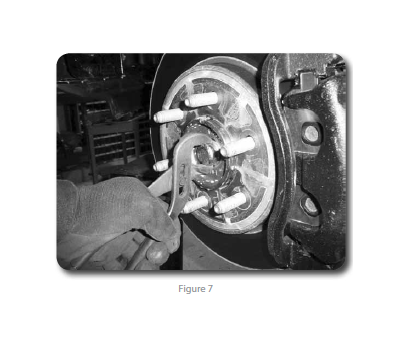
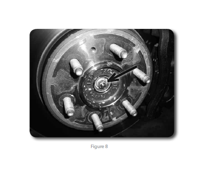
13. Carefully remove the hub dust cap to expose the axle shaft nut Figures 7/8. Remove the nut. Retain the cap and nut, they will be reinstalled later.
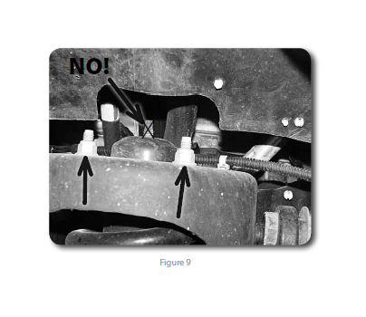
14. Loosen but do not remove the three strut assembly mounting nuts at the frame
Figure 9. Do not loosen the middle strut nut.
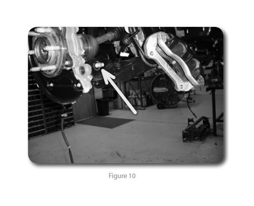
15. Loosen and remove the nut from the strut-to-lower control arm mounting bolt
Figure 10. Leave the bolt in place at this time. Retain the mounting nut.
16. Remove the upper and lower ball joint nuts Figure 11 and reinstall a few turns.
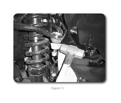
17. Strike the knuckle near the upper and lower ball joints to dislodge the joints
from the knuckle.
18. Remove the upper ball joint and the strut-to-lower control arm bolt. Swing the
knuckle/lower control arm down to remove the CV shaft from the hub. Retain
ball joint nut and strut bolt.
19. Remove the lower ball joint nut and remove the knuckle from the vehicle. Retain
hardware.
20. Remove the lower control arm mounting bolts and remove the lower control arm
from the vehicle. Retain hardware.
21. Mark the struts to distinguish between driver's and passenger's.
22. Remove the three strut assembly mounting nuts at the frame and remove the
strut assembly from the vehicle.
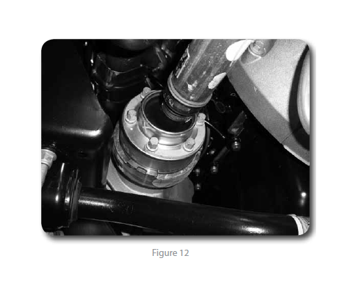
23. Remove the driveshaft mounting bolts and disconnect the driveshaft from the
differential Figure 12. Allow the driveshaft to rest out of the way.
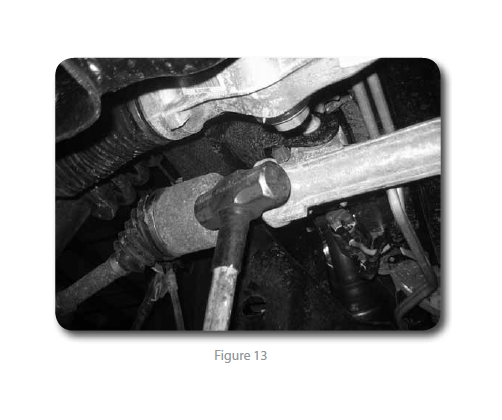
24. Remove the passenger's side CV shaft. Strike the shaft with a hammer to dislodge
it from the splines. This will make handling the differential much easier.
Figure 13
25. Support the front differential with an appropriate jack. Loosen all of the hardware
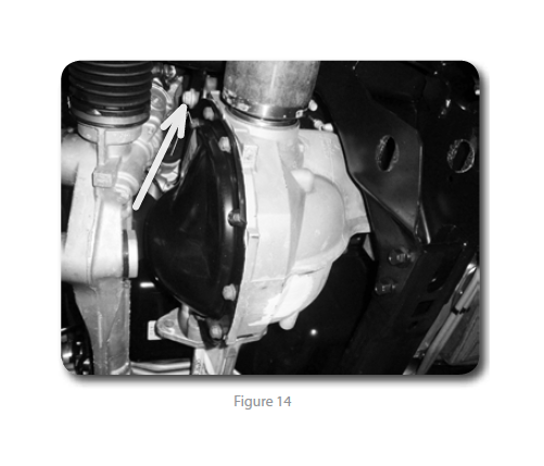
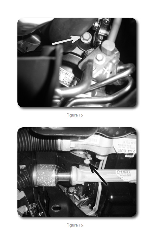
and slide the differential all the way to the passenger's side. Orientate the joint at the steering rack so there is the most possible clearance to remove the front driver's side bolt. Remove this bolt first. Disconnect the differential breather hose from the differential housing. Remove the rear driver’s side and one passenger’s side differential mounting bolts Figure 14 / 15 / 16 and remove the differential from the vehicle.
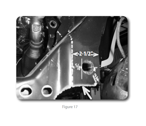
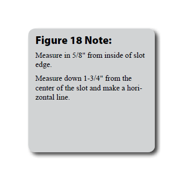
26. The driver’s side rear lower control arm frame pocket must be modified to provide clearance for the differential in its relocated position. On the front side measure from the inside edge of the factory control arm slot 5/8" Figure 17. Make a vertical cut line at the mark. Measure down 1-3/4" from the center of the slot, make a horizontal cut line.
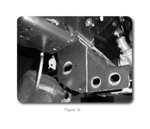
27. On the back side measure from the outside edge of the control arm slot 4-1/2" and mark Figure 18. Make a vertical cut line at the mark.
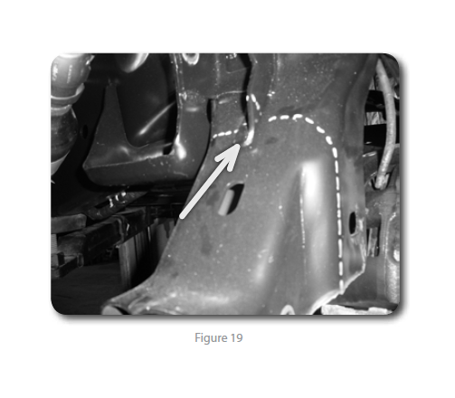
28. On the 'inside' face, measure up 3/4" from the bottom of the original diff mount bracket. Draw a horizontal line to the front and rear face. Figures 19
29. Trim the area from the vehicle.
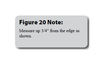
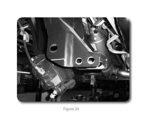
30. The passenger's side control arm pocket must also be trimmed. Measure down
1-3/4" and make a horizontal cut line. The cut will stop where the vertical offset
begins, taper the cut as shown. Figure 20
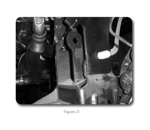
31. Install the rear crossmember Figure 21
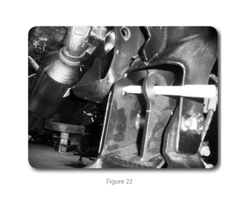
32. With the crossmember installed mark the differential hole on the factory control
arm bracket. Remove the crossmember and drill a 5/8" hole at the mark, for
easiest access drill the hole from front to back. Figure 22
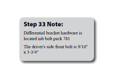
33. Install the passenger side and front driver side differential brackets onto the
differential, run the provided 9/16" hardware from front to rear for clearance to
the steering rack.
34. Loosely install the new differential drop brackets in the passenger’s side and
front driver’s side factory differential mounting locations with the factory hardware.
The brackets should offset toward the front of the vehicle when properly
installed.
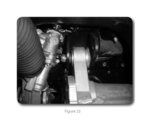
35. Raise the differential in the vehicle by aligning the OE differential mounts to the
two front drop brackets. Attach the brackets to the frame with the OE hardware.
Figure 23
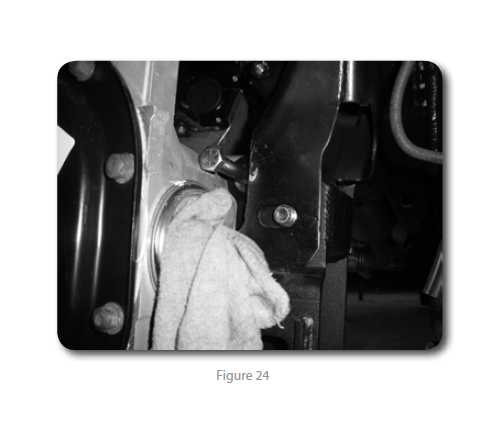
36. Install the new rear crossmember in the rear lower control arm frame pockets
and fasten with new 18mm bolts and washers (do not put nuts on at this time).
Run bolts from front to rear. Leave hardware loose. Ensure the hole that was
drilled in the frame pocket lines up to the differential mounting hole in the
bracket. Figure 24
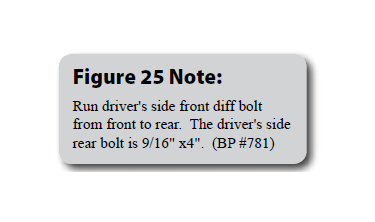
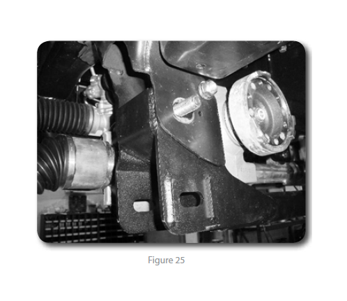
37. Fasten the differential to the rear crossmember Figure 25 with a 9/16" bolt, washers,
and nut. Run the bolt from front to rear. Leave hardware loose.
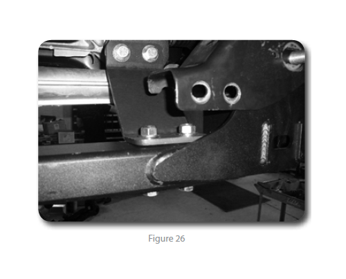
38. Install the offset differential support bracket to the passenger’s side differential
bracket using 9/16" hardware and 1/2" x 3" hardware to the crossmember. The
horizontal slots will be located up at the differential. Leave hardware loose.
Figure 26
39. Go back and torque all the differential mounting hardware (9/16" and 14mm) to
95 ft-lbs (6 bolts total). Remove the elbow from the vent line and attach the differential
hose extenstion to the line and to the differential.
40. Install the front crossmember in the front lower control arm pockets and fasten
with the OE lower control arm hardware. Leave hardware loose.
41. Install the lower control arms in the new crossmembers and fasten with the provided
18mm cam bolts, cam washers and 18mm nuts. Run the front bolts from front to rear and leave loose. Run the rear bolts from rear to front. The main body of the cam will be 'up' in the cam slot
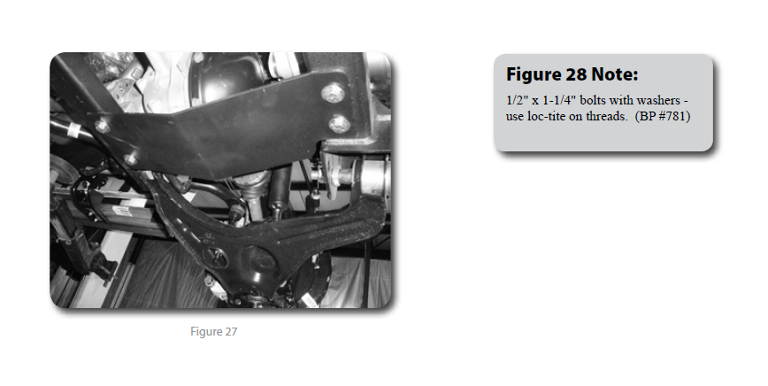
42. Install the provided differential skid plate to the front and rear crossmembers
with ½” x 1-1/4” bolts and ½” SAE washers into the threaded holes in the crossmembers Figure 27. Leave hardware loose.
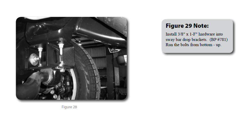
43. Install the sway bar drop brackets with new 3/8" x 1-1/4" hardware, snug but
do not tighten at this time. Attach the crossmember 18mm nut with 3/4" USS
washer. Note: Use a ratchet extension through the lower slots to access the hardware
Figures 28
44. With the lower control arms installed, go back and torque the four crossmember mounting bolts to 222 ft-lbs. Ensure that the front crossmember is centered in the vehicle. Torque the differential skid plate bolts to 65 ft-lbs. Tighten sway bar drop hardware to 35 ft-lbs.
45. Place the upper strut spacers on top of the factory struts with factory hardware.
Tighten the factory nuts to 40 ft-lbs.
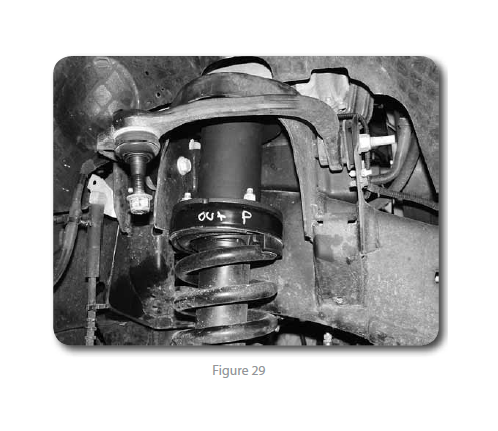
46. Loosely install the strut assembly with new 7/16" nuts and washers on top of the
frame strut mount. Figure 29
47. Reinstall the passengers side CV.
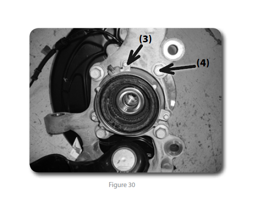
48. Remove the four hub bolts from the knuckle and remove the hub from the
knuckle Figure 30. Inspect mounting surface of the hub assembly and clean any
dirt or corrosion off as necessary.
49. Install the hub into the corresponding new knuckle and fasten with the factory
bolts. The ABS wire will be located at the 'top' of the hub. Use Loctite on the
bolt threads and torque to 148 ft-lbs.
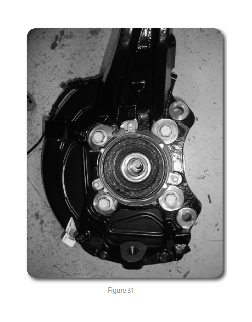
50. Remove the three 6mm bolts mounting the vacuum hub assembly to the inside
of the factory knuckle Figure 31. Transfer the vaccum assembly over to the new
knuckle. Make sure the vacuum port is pointing towards the top. Attach with the
factory bolts, tighten bolts securely (about 5-7 ft-lbs).
51. Install the dust shield with the factory 6mm bolts, tighten bolts securely (about
5-7 ft-lbs). Route the ABS cable behind the dust shield.
52. Install the new knuckle assembly on the lower control arm ball joint and loosely
fasten with the original nut. Install the CV shaft in the hub, swing the whole assembly
up and attach the lower control arm to the strut with the original hardware.
Leave all hardware loose.
53. Attach the upper control arm to the knuckle with the original nut. Torque the upper
ball joint to 85 ft-lbs and the lower ball joint to 111 ft-lbs.
54. Torque the upper strut nuts to 50 ft-lbs. Torque the lower strut bolts to 80 ft-lbs.
55. Fasten the CV shaft to the hub with the original nut. Make sure the splines are
engaged properly in the vacuum actuated section of the hub. The hub should
have a very minor amount of rotational play with the CV shaft if installed properly,
torque to 20 ft-lbs. Reinstall the dust cap.
56. Install tie rod from top-down. Torque to 111 ft-lbs.
57. Install the brake rotor and caliper to the knuckle with OE bolts. Torque to 148
ft-lbs.
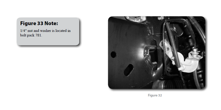
58. Install the brake line relocation brackets at the frame. Attach with factory hardware
to frame, attach brakeline retaining clip with 1/4" nut and washer to the
relocation bracket. Tighten to 15 ft-lbs. Figures 32
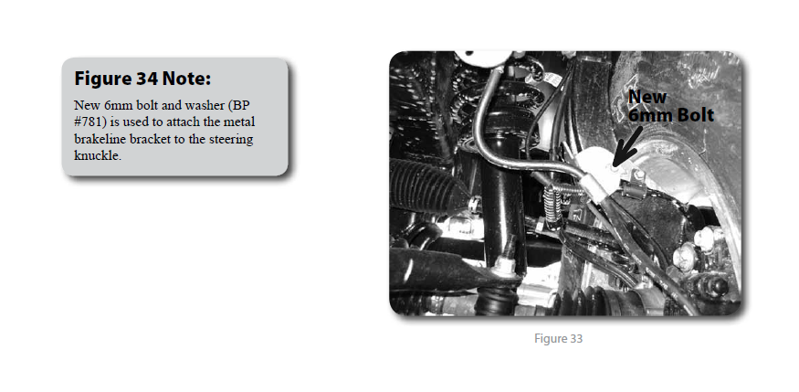
59. Attach the ABS line to the connector at the inner fender and the vacuum line
to the hub. Route the lines similar to the factory setup down to the side of the
knuckle. Attach the ABS wire with the factory 6mm bolt to the side of the
knuckle. Attach the brakeline with a new 6mm x 18mm bolt with 1/4" washer
to the side of the knuckle, the brakeline locating tab will go into the unthreaded
hole. Figures 33
60. Install the sway bar to the new sway bar drop brackets with 7/16” x 1-1/4”
hardware. Attach the sway bar to the sway bar end links with the original
hardware. Torque the 7/16” hardware to 45 ft-lbs. Torque sway bar link nut to 45
ft-lbs.
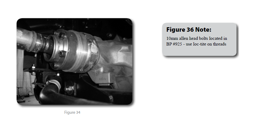
61. Install the supplied driveshaft spacer and reattach front driveshaft to differential
with new hardware. Torque bolts to 76 ft-lbs. Figure 34
62. Install the wheels and lower the vehicle to the ground.
63. Bounce the front of the vehicle to settle the suspension. Center the lower control
arm cams and torque to 150 ft-lbs. Adjust the toe before driving it to an alignment
shop.
64. Check all hardware for proper torque.
»Rear Installation
1. Block the front wheels and raise the rear of the vehicle. Place jack stands under
the frame rails ahead of the spring hangers.
2. Remove the wheels.
3. The parking brake cable must be relocated. To disconnect the cable from the
frame first pull down on the cable and clamp it off with vise grips near the
middle of the frame Figure 1. This will gain slack to disconnect the driver’s side
rear cable from the main (passenger’s side) cable.
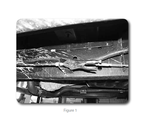
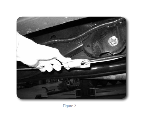
Remove the driver’s side parking brake cable from the junction bracket. Figure 2
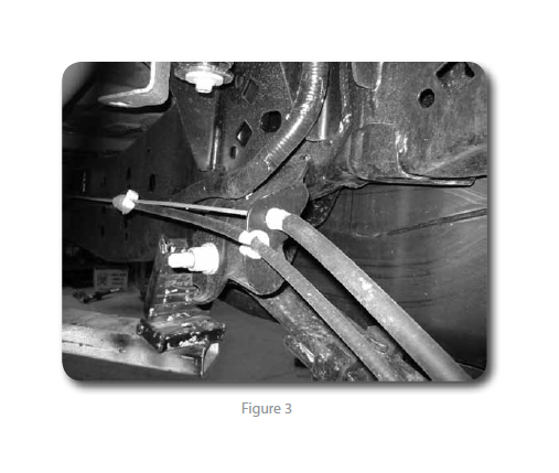
4. Compress the retaining tabs and remove the driver’s side cable from the spring
hanger Figure 3. It will be relocated and reconnected later.
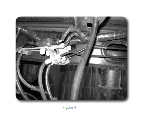
5. Disconnect the rear brake line from the frame. Figure 4
6. Support the rear axle with a hydraulic jack. Remove the factory shocks. Retain
mounting hardware.
Note: Perform the rear installation on one side at a time.
7. Remove the passenger’s side u-bolts.
8. Lower the axle and remove the factory lift block, it will not be reused.
9. For 5" rear block kits follow steps 11-14. 4" kits, skip ahead to step 15
10. Using C-clamps, clamp the leaf spring pack together on each side of the center
pins. Remove the center pins and discard.
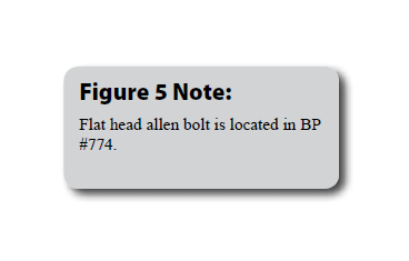
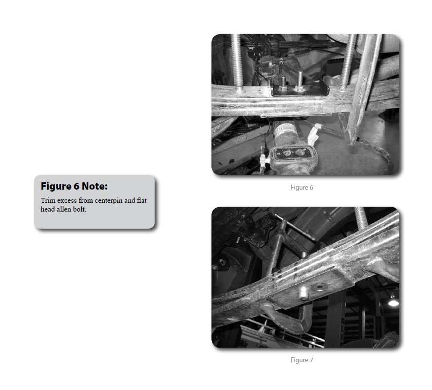
11. Place the plate on the bottom of the leaf pack and secure with new center pin
in the 'forward' hole and flat head allen bolt through the 'rear' hole. Install new
u-bolt reatining plate on top, it will be offset 'forward'. Tighten to 35 ft-lbs.
Figures 5 / 6 / 7
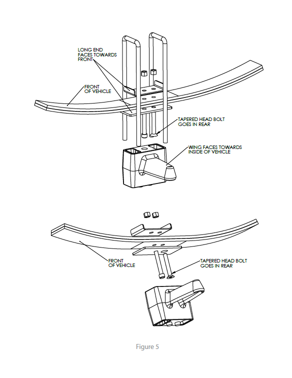
12. Install the new provided lift block so that the bump stop wing goes toward the
inside of the vehicle. The block will use the both of the lower center pin holes.
The upper only uses 1 hole which will shift the axle slightly forward.
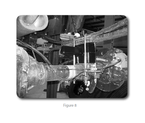
13. Raise the axle/block to the spring while aligning the center pin. Fasten the
spring/block assembly with the provided u-bolts, high nuts and washers. Snug ubolts,
they will be torque with the weight of the vehicle on the springs. Figure 8
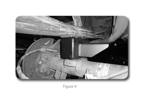
14. Install the new bump stop as shown Figure 9. The gusset on the wing will face
towards the front of the vehicle. The part # is stamped on the bump stop wing.
Part # 02429 = Driver's side, #02430 = Pass side.
15. Raise the axle and align the center pins. Fasten the assembly with new u-bolts,
high nuts, and washers. Snug - ubolts, do not tighten at this time. They will be
tightened with the weight of the vehicle on the springs.
16. Repeat installation procedure on the driver’s side of the vehicle.
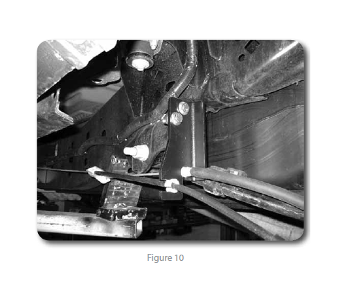
17. Install the provided parking brake relocation bracket to the driver’s side front
spring hanger using 7/16" bolts, washers, and nuts. Figure 10
18. Reconnect the parking brake cable at the junction. When reconnected, remove
the clamp to allow the cable to return to its normal tension. Attach the parking
brake cable through the relocation bracket through the slot in the bottom.
Models with Ford's electric retracting steps will need to order an extra relocation
bracket, available separately. The steps can be temporarily disabled until the
new bracket is installed. Feature is controlled in the instrument cluster computer.
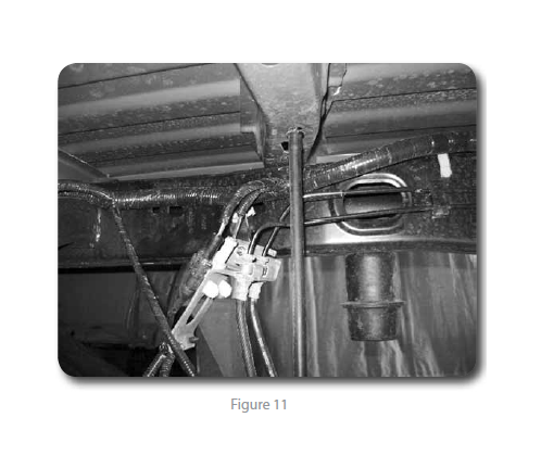
19. Install the provided brake line relocation bracket to the driver’s side frame rail
with the factory brake line bracket bolt Figure 11. Torque to 15 ft-lbs.
20. Attach the brake line to the relocation bracket with a ¼” nut and ¼” USS washer.
It may be necessary to rotate the OE brakeline clip bracket to have the lines face
'down' for adequate slack. Torque to 15 ft-lbs.
21. Install the new shocks with the OE hardware. Torque to 60 ft-lbs.
22. Check all lines/wires for proper slack.
23. If the vehicle is equpped with EPAS, reconnect the power steering control module
connector.
24. Install the wheels and lower the vehicle to the ground.
25. Bounce the rear of the vehicle to settle the suspension.
26. Torque the u-bolts to 100-120 ft-lbs.
27. Check all hardware for proper torque
28. Check hardware after 500 miles.
29. A complete front end alignment is necessary.
30. Adjust headlights.
Post-Installation Warnings
1. Check all fasteners for proper torque. Check to ensure for adequate clearance between all rotating, mobile, fixed, and heated members. Verify clearance between exhaust and brake lines, fuel lines, fuel tank, floor boards and wiring harness. Check steering gear for clearance. Test and inspect brake system.
2. Perform steering sweep to ensure front brake hoses have adequate slack and do not contact any rotating, mobile or heated members. Inspect rear brake hoses at full extension for adequate slack. Failure to perform hose check/ replacement may result in component failure.
3. Perform head light check and adjustment.
4. Re-torque all fasteners after 500 miles. Always inspect fasteners and components during routine servicing.

