How to Install Vision X Optimus LED Fog Light Mounting Brackets (2017 Raptor) on your Ford F-150
Shop Parts in this Guide
PREPARATION
1. We recommend completely reading instructions before installing.
2. Consult your local state regulatory agency regarding the use of LED lighting.
3. The placement of LED lighting should not restrict airflow to the radiator, or block head lamps, turn signals, or parking lights.
MAINTENANCE
1. All Vision X models have been designed for maintenance free use. In the case an LED lamp or other part replacement is needed please contact your authorized service center.
WARNINGS
As with many other high-tech products, this VISION X LED requires a bit of attention before you can use it. Please read the accompanying information carefully first.
1. Don't stare directly into the light or shine directly into the eyes of another person as this may cause temporary loss of vision.
2. Never disassemble the products, as all parts must be factory serviced to ensure proper operation.
3. Don't interchange the parts inside this light with other products.
4. The LED light is to be mounted on the vehicle only in a vertical, bottom mounting, or in a suspended position.
5. After turning on the light, the body might be hot enough to warrant a burn risk. Be careful when you touch the body after turning on the light for a long period of time.
6. Use the supplied wire harness for electrical installation.
7. The LED light must not adversely affect the performance of low beam, high beam, engine cooling or the driver's view.
WARNING: Bolts, Nuts, and Washers are Stainless Steel. DO NOT USE Pneumatic or Electric Tools to Tighten and Loosen. The Hardware Will Permanently Lock Together.
MOUNTING INSTALLATION
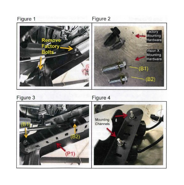
1. Behind the lower air dam on top of the opening locate and remove the 2 bolts needed to install the Fog light kit. One bolt is a [M8] the other a [M6] See [Figure 1].
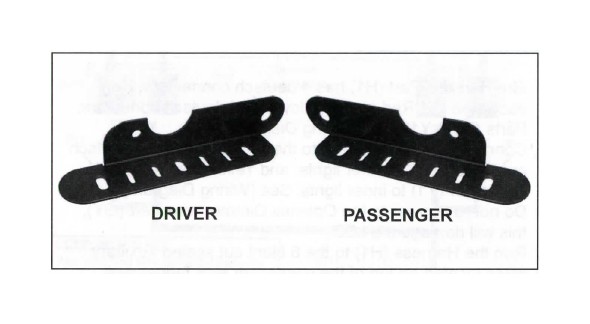
2. Mount the fog light bracket Part (P1) to the truck using the bolts Part (B1) and Part (B2) supplied in the kit as the factory bolts are too short. See [Figure 2 & 3]
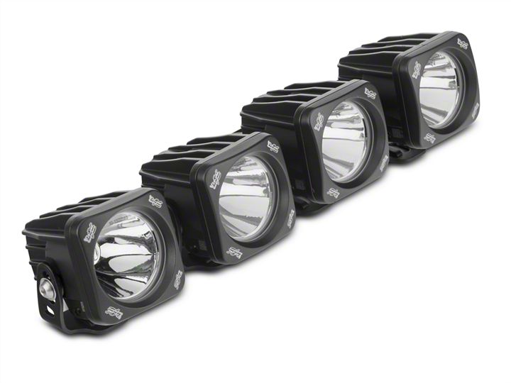
3. Assemble 2 lights per side through the channels of the bracket, see [Figure 4]. Stagger and angle the lights to be facing forward.
4. Repeat the previous steps for the second bracket.
LIGHT ANGLE ADJUSTMENT
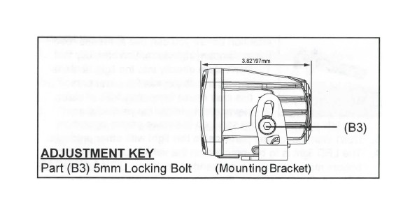
1. Use the 5mm Allen Key Part (A1) to loosen the Allen Head Bolts Part (B3) on each light.
2. Adjust the light until you have your desired angle.
3. Tighten the Allen Head Bolts to hold the desired position.
ADDITIONAL INFORMATION
If needed, additional information and related products, as well as a digital copy of these instructions, can be located online at www.visionxusa.com
WIRING INSTALLATION:
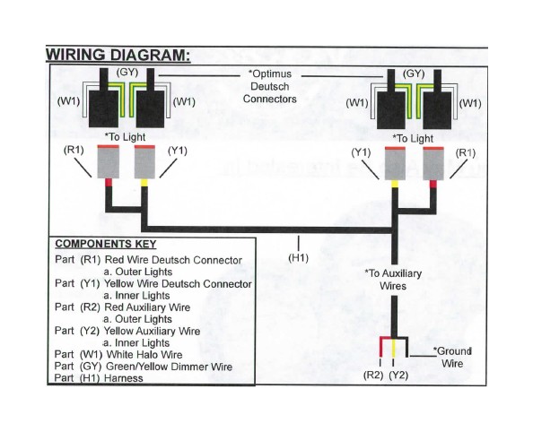
1. The Harness Part (H1) has 4 deutsch connectors. For each side is 1 Red and 1 Yellow wired deutsch connector. Parts (R1 & Y1). See [Wiring Diagram].
2. Connect the Harness (H1) to the lights. Red wired deutsch connector (R1) to outer lights, and Yellow wired deutsch connector (Y1) to inner lights. See [Wiring Diagram].
3. Do not run power to the Optimus Dimmer wire Part (GY), this will damage the LED.
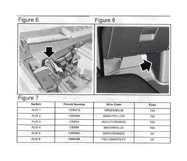
4. Run the Harness (H1) to the 6 blunt cut sealed auxiliary wires located on top of the passenger side fender well. See [Figure 5].
5. Amperage is IMPORTANT, please refer to your owners manual or see [Figure 7] for relay code/auxiliary guide before wiring.
6. For all lights controlled by 1 switch connect the Red wire Part (R2), and Yellow wire Part (Y2) to the Brown/Blue auxiliary wire (AUX4). For the outer and inner lights controlled by 2 switches connect the Red wire (R2) to the Violet/Orange auxiliary wire (AUX3), and the Yellow wire (Y2) to the Brown/Blue auxiliary wire (AUX4). See [Figure7].
7. For Halo wire operation Part (W1) must be connected to a 12v source. Please consult your owners manual or installation professional.
8. Ground the Black wire to chassis.
9. Behind the passenger side kick panel you'll find 6 colored auxiliary wires, these wires run to your switches in the cab, see [Figure 6]. Depending on where your truck was manufactured is whether or not these wires are connected to the 6 colored auxiliary wires running from under the hood, see [Figure 5]. Make note of the guide [Figure 7] to ensure the correct wire colors are connected to each other in order for the switches to work.
10. Test lights.
