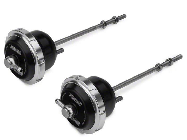
How to Install Turbosmart IWG75 Internal Wastegate - 5 PSI - Pair on your F-150
Shop Parts in this Guide
RECOMMENDATIONS -
Turbosmart recommends that boost pressure is set using a Dynamometer and not on public roads. - Turbosmart recommends that the engines Air/Fuel ratio is checked while setting the desired boost pressure, as any increase in boost pressure can cause the engine to run “LEAN”, resulting in possible engine damage.
MOUNTING YOUR IWG75 (non-clevis type)
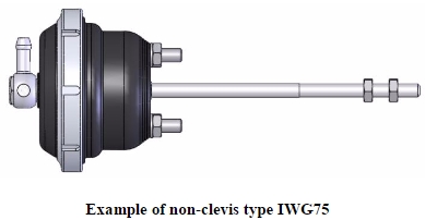
The mounting screws are 32mm apart, use the supplied M6 spring washers and nuts to secure the internal wastegate actuator onto the compressor cover of your turbocharger. The supplied internal wastegate actuator does NOT include a clevis as shown above. The rod is fastened to the wastegate flap by the two M6 nuts installed on the rod. The thread is M6x1.0.
Non-Clevis Type Actuator
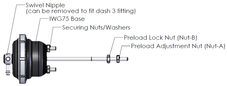
For a non-clevis type actuator, the preload is set by adjusting both of the M6 nuts together accordingly. The thread on the rod is M6x1.0 which means that one full turn of the nut equals 1mm change in rod extension, hence 1mm of preload. To set preload, hand-tighten the preload adjustment nut (nut A) clockwise to hold the wastegate flap shut. Now, use a 10mm spanner to turn nut-A two complete turns in a clockwise direction. The preload is now set to 2 mm. To lock the preload setting, tighten the preload lock nut (Nut-B) in an anticlockwise direction until it is hand-tight against the wastegate valve arm. Use a torque wrench to tighten both nuts to 6.5Nm (4.79 ftlb). Confirm that preload is set correctly by applying air pressure (do not apply air pressure supply higher than 3 bar (40psi) gauge) to the top cap of the IWG, the rod should move without hesitation once the air pressure applied to the cap of IWG is higher than the spring pressure.
ACHIEVING YOUR TARGET BOOST PRESSURE
There are various factors involved in achieving your target boost pressure including. - The size of the spring fitted in your wastegate actuator i.e. the boost pressure achieved by the wastegate actuator spring only. - The desired level of boost pressure and the difference between this and your wastegate spring pressure. - The size of your turbocharger and wastegate and the resulting exhaust manifold backpressure in your system. Turbosmart recommends the ideal setup for achieving your target boost pressure is to use the wastegate actuator in conjunction with a Turbosmart boost controller.
IMPORTANT NOTES ON SETTING THE WASTEGATE ACTUATOR SPRING PRESSURE
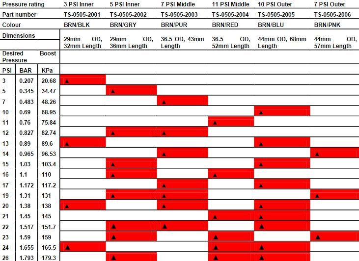
A stiffer spring should only be used when necessary. The wastegate actuator allows for different combinations of spring pressures. All springs that are adaptable with the wastegate actuator are shown in the table below. The tuner can use combinations of up to 3 springs to achieve the following base boost pressures. To aid in the identification of these springs they are supplied colour coded. If this colour coding is not clear please use the dimensions in the following table to identify the spring. Please see the following detailed instructions on setting your wastegate actuator spring pressure. The springs chosen should be rated to the lowest boost level desired. Notes:
1. As a rough guide it is possible to double the base pressure when accompanying a Turbosmart IWG75 with a Turbosmart boost controller if the system is adequately sized. Results will vary depending on every application.
2. Check the spring combination in your IWG75. If more springs are required, they can purchased from your Turbosmart dealer by using the TS-xxx-xxxx part numbers shown below each spring.
Changing the springs
WARNING! Fitting a wastegate actuator with a higher spring pressure may cause a higher than expected increase in boost pressure. Turbosmart recommends adjusting your boost controller back to its minimum setting and measuring the new minimum boost pressure achieved by the new spring, before increasing your boost pressure again.
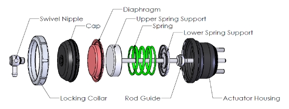
IMPORTANT: A press or clamping device must be used when removing or installing the collar as clamping the cap down removes the load off the collar from the spring and allows the collar to be removed.
1. If the engine has been running, allow it to cool down before removing the actuator from its bracket.
2. Use a press or a vice to clamp down the cap to the body and remove collar.
3. Remove the actuator from the clamping device carefully as the cap is under spring load.
4. Remove cap, diaphragm and upper spring support with rod.
5. Change the springs making sure that they sit in the right grooves in the lower spring support
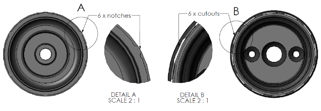
6. Reassemble in reverse order. Ensure that the diaphragm is installed in the centre of the upper spring support and when installing the cap, make sure that the cap and diaphragm are centred and that the locating notches on the cap match the cut-outs in the lower housing.
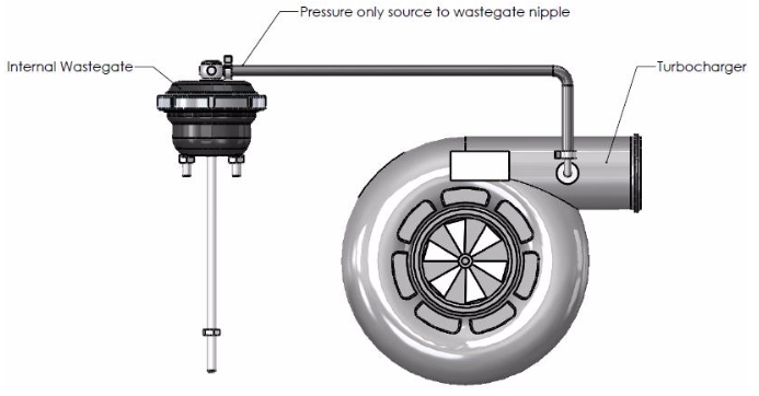
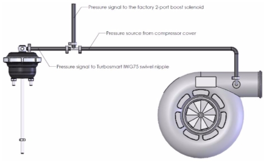
NOTES ON BOOST CONTROL HOOKUP WARNING! Changing your connection method can cause a higher than expected increase in boost pressure. Turbosmart recommends adjusting your boost controller back to its minimum setting and measuring the new minimum boost pressure achieved by the new setup before increasing your boost again. Basic setup If no boost controller is being used connect the BOOST PRESSURE ONLY SOURCE to the wastegate actuator pressure nipple as shown.
Note: Some vehicles are fitted with a “tee” type inlet port on the for the internal waste gate actuator. In such applications, when upgrading to a Turbosmart IWG75, use a hose tee-piece to supply a pressure signal to both the internal wastegate actuator and the factory 2 port boost solenoid
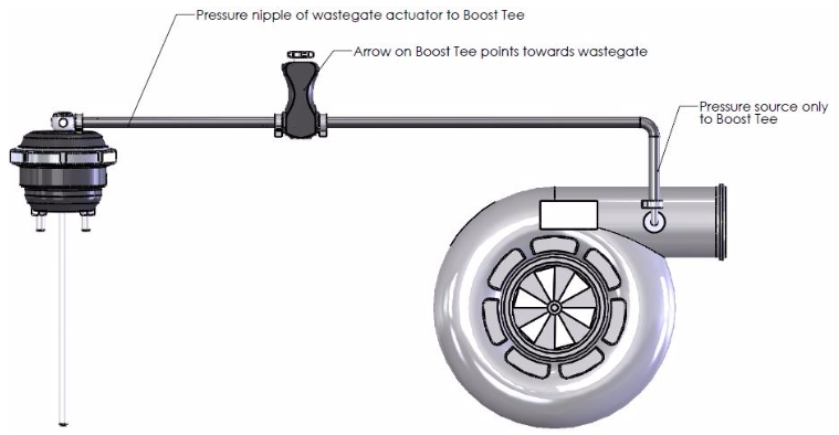
Boost Tee setup When using your wastegate actuator in conjunction with a Turbosmart Boost Tee, fit the controller between the boost pressure source and pressure nipple as shown. Ensure the arrow on the Boost Tee is pointing in the direction illustrated. Refer to the instructions supplied with your Boost Tee for further detail if necessary.
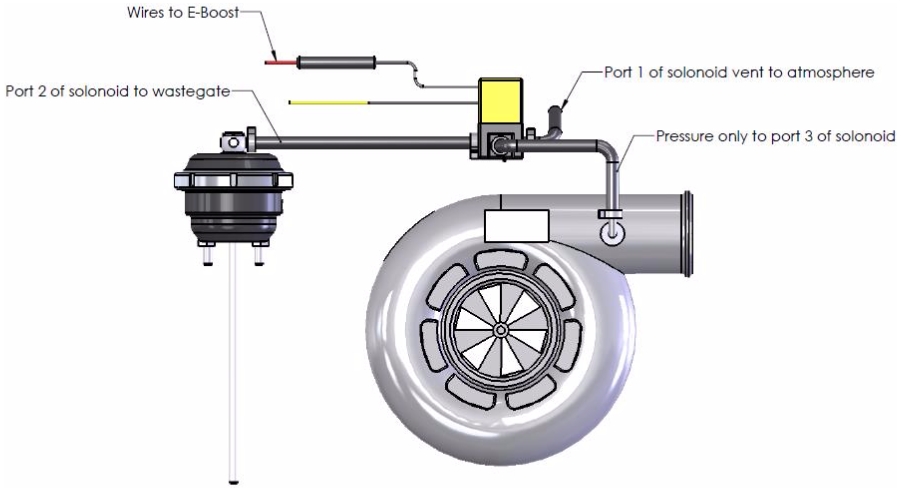
E-Boost connection methods Turbosmart recommends using the wastegate actuator in conjunction with the Turbosmart E-Boost. E-Boost connection Method
Port 1 of solenoid vent to atmosphere
Port 2 of solenoid to pressure nipple of wastegate actuator
Port 3 of solenoid to Pressure only source
