How to Install Stainless Works 1-7/8 in. Headers w/ Catted Y-Pipe - Factory Connect on your F-150

Shop Parts in this Guide
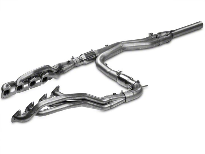
Thanks for purchasing Stainless Works Muscleflow Headers for your Ford F-150 Raptor. We have gone to great pains to make sure that our exhaust systems fit and sound great. Please follow these steps to ensure that your installation goes as planned.
1. Stainless Works recommends the use of Hi-Temp RTV silicon gasket maker as an option to or in conjunction with the use of factory gaskets. The recommended RTV is Sensor- Safe Valco All-in-one Aluminum or Permatex P/N 101BR or 27BR, available at NAPA and other retailers.
2. Disconnect the battery before starting work on the exhaust system for your vehicle.
3. Your exhaust system can be installed by a weekend warrior but the use of a lift is
recommended for ease of installation. If using a jack, the vehicle must be placed on a
level hard surface and jack stands are required for safety reasons.
DISASSEMBLY
4. Raise and support the vehicle.
5. Remove the air box and inlet.
6. Remove engine skid plates (10) 10 mm bolts.
7. Loosen the factory exhaust at the 2 bolt flange (2) 10 mm bolts.
FOR CONNECTION TO FACTORY EXHAUST
8. Loosen clamp at slip fit connection point (behind the 2 bolt flange connection
point) and remove the front section of pipe between the 2 bolt flange connection
and the slip joint.
FOR CONNECTION TO STAINLESS WORKS EXHAUST
9. Remove exhaust from all hangers then remove from truck.
10. Remove skid plate on left side of transmission cross member, (4) 8 mm bolts.
11. The following instructions are required only if you are planning to save the factory
exhaust, otherwise skip to line #21
12. Remove (2) 6 mm bolts holding left and right heat shields to transmission cross member.
13. Support transmission and transfer case with jack stands.
14. Remove (2) 12 mm nuts from transmission mount.
15. Remove (4) 12 mm bolts and nuts from cross member and remove cross member.
16. Remove (1) 10 mm bolt from left Y pipe hanger.
17. Loosen clamp on left head pipe.
18. Unplug all O2 sensors.
19. Remove (2) 10mm nuts from left and (2) 10 mm nuts from right head pipes and remove head pipes.
20. Re-install cross member and mount and tighten.
21. If you are not planning to save the old exhaust, you can simply cut hangers from Y-pipe to simplify removal of manifold pipes.
FOR CONNECTION TO ANY EXHAUST SYSTEM
22. Remove heat shield around front axle (1) 10mm nut (1) 8 mm nut.
23. Remove remaining (2) 6mm bolts from right heat shield and slide heat shield back toward the rear of the vehicle.
24. Remove starter and wires (1) 6 mm nut (2) 8 mm nuts and (3) 8 mm bolts.
25. Mark steering shaft for later reinstallation to same markings, and remove (1) 10 mm bolt from upper U-joint and move out of the way.
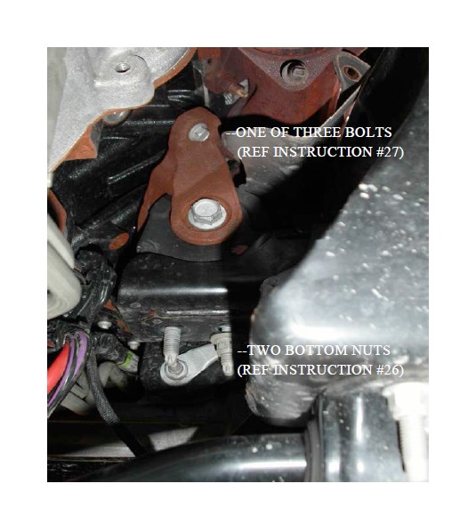
26. Remove (2) 14 mm nuts from right motor mount. See picture below showing one nut removed and one loose.

27. Raise motor with jack and remove (3) 8 mm bolts from right motor mount to engine
plate. The picture above shows the single bolt at the rear of this motor mount. There are two more at the front of this motor mount. See picture above.
28. Remove right and left heat shields on manifolds (4) 6 mm bolts two per side.
29. Remove (1) 6 mm bolt from dipstick tube and remove dipstick and tube.
30. Remove (16) 10 mm nuts, eight per side from manifolds and remove manifolds.
31. If you are planning to use aftermarket header bolts, remove the 16 studs at this time. The use of aftermarket bolts is not necessary, but will improve the process of tightening the headers and future removal/ assembly of the headers. If you plan to keep the studs, you will need to remove the top two back studs on the driver side and all the top studs on the passenger side. This requires a Torx E8 socket or wrench for removal.
32. Seal headers with RTV, allow the RTV to get tacky (about 15 minutes) and install using remaining studs and nuts. Torque to OEM specifications.
33. Re-install dipstick tube and dipstick.
34. Re-install motor mount and lower the motor and tighten nuts.
35. Re-install starter.
36. Re-install axle shield.
37. Re-install steering shaft.
38. Re-install right heat shield.
39. Re-install air box.
40. Re-install (1) 6 mm bolt back in left heat shield at cross member.
41. Install left lead pipe to header with (1) 3” clamp
42. Install catalytic converter or cat eliminator to left lead pipe.
43. Install rear left lead pipe to cat with 3” clamp with wire hanger.
44. Re-install left hanger to transmission grommet with (1) 3” clamp.
45. Install right catalytic converter or cat eliminator to header with one 3” clamp.
46. Re-install all skid plates.
47. Remove O2 sensors from old pipes and re-install in new pipes. Note that an O2 extension is provided for use with the left rear O2 sensor – install now. The P/N for the O2 sensor extension for 2010 trucks is P/N 109014 from Caspers Electronics. For 2011 trucks a different sensor extension is required (P/N 109214R). This sensor will have the two external nubs removed from the male end. You will have to file off the two nubs on the male end of the mating male wire end so it can slip into the female end of this extension.
48. Install and secure the wires away from the driveshaft using zipties.
49. Re-install all skid plates.
FOR HEADERS TO FACTORY EXHAUST
50. Install factory Y-pipe using (2) 3” clamps.
51. Reconnect to factory exhaust using 3” clamp.
52. Install X pipe using (2) 3” clamps. This step is not required for the Raptor Truck
Lightning style exhaust which exits in front of the rear tires (P/N FTRPT10CBFT).
53. Next follow the instructions for catback installation omitting the Y-pipe installation in the catback.
54. Re-connect battery. Be sure to have adequate clearance around all wires, hoses and lines. If anything is in contact with the exhaust system, it will melt. Make sure to have at least ½” of clearance and wrap any suspect areas with DEI thermal barrier wrap.
55. After double checking for clearance and making sure all lines, wires and hoses are
secured, drive the car for 10-20 miles and re-check all clamps and clearances. Your
system may be tack welded at the joints/ clamps to reduce shifting of the system during heating and cooling cycles. Make certain to disconnect the battery before performing any welding.

