How to Install SkyJacker 6 in. LeDuc Series Coil Over Lift Kit w/ M95 MonoTube Shocks on your F-150
Installation Time
1 days
Tools Required
- Metric / Standard Wrenches & Sockets
- Floor Jack
- Jack Stands
- Measuring Tape
- Torsion Bar Tool
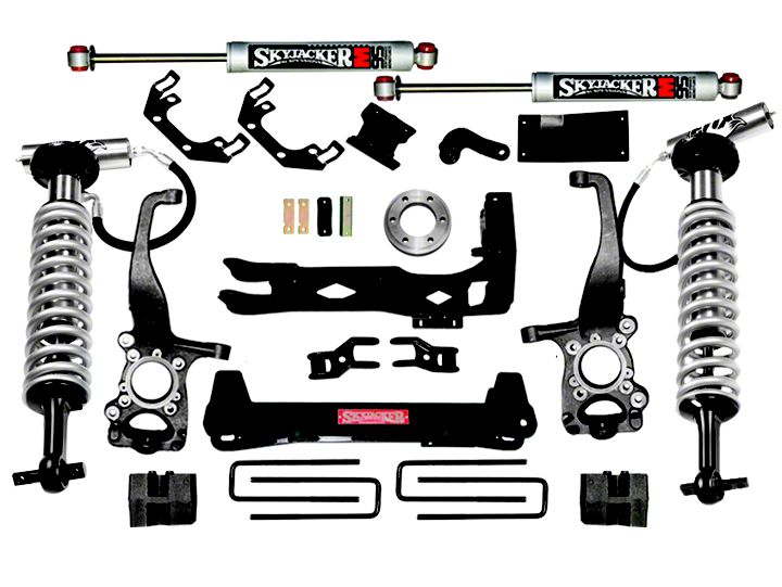
Shop Parts in this Guide
Before beginning the installation, thoroughly & completely read these instructions, the enclosed driver’s WARNING NOTICE & affix the WARNING decal in the passenger compartment in clear view of all occupants. Please refer to the Parts List to insure that all parts & hardware are received prior to the disassembly of the vehicle. If any parts are found to be missing, contact SKYJACKER® Customer Service at 318-388-0816 to obtain the needed items. If you have any questions or reservations about installing this lift kit, call SKYJACKER® Technical Assistance at 318-388-0816.
Make sure you park the vehicle on a level concrete or asphalt surface. Many times a vehicle is not level (side-to-side) from the factory & is usually not noticed until a lift kit has been installed which makes the difference more visible. Using a measuring tape, measure the front & rear (both sides) from the ground up to the center of the fender opening above the axle. Record this information below for future reference.

IMPORTANT NOTES:
• If larger tires (10% more than the stock diameter) are installed, speedometer recalibration will be necessary. Contact your local Ford dealer or an authorized dealer for details.
• After installation a qualified alignment facility is required to align the vehicle to factory
specifications.

IMPORTANT: The net amount of ride height increase depends upon the age & use of the vehicle, wheel offset, & numerous other factors. Stated torsion bar ride height increases are based upon the factory specifications. If the torsion bars were “cranked up” at some point in the past, expect a corresponding reduction in overall height increase with the new torsion keys.
NOTE: The torsion bars, like any other spring, are subject to fatigue & sagging over time. Also, torsion bars have different ratings depending on how the vehicle was equipped from the factory. In some cases, installing heavier rated bars (which can be purchased from a Ford dealer) may be the only solution to regaining ride height lost from adding heavy aftermarket accessories, such as a winch bumper or snow plow.
NOTE: Various types of torsion bar puller tools are available, however, due to the extreme loads present in torsion bar suspension systems, we have found the two-jaw style tool that clamps to the crossmember tends to slip & damage the crossmember. A C-clamp style puller tool is preferred & available through various tool companies such as Snap-On,etc.
FINAL NOTES:
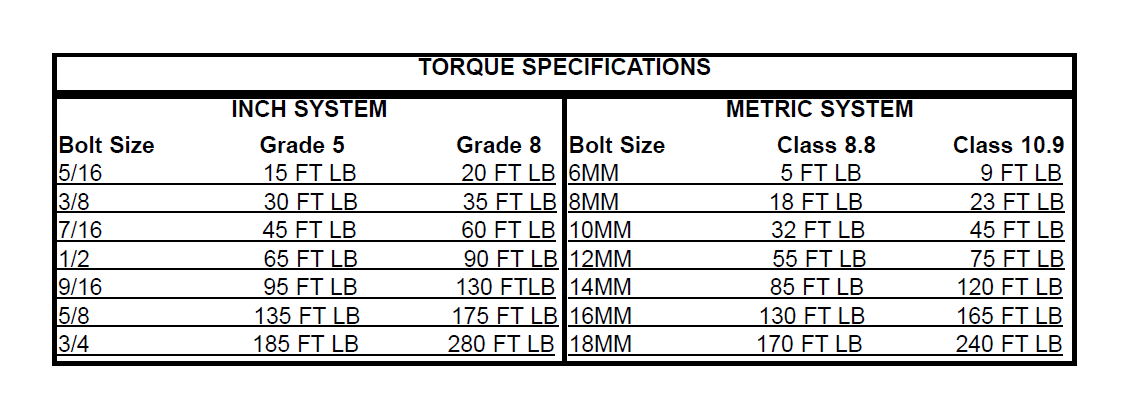
• After the installation is complete, double check that all nuts & bolts are tight. Refer to the following chart again for the proper torque specifications. (Do not retighten the nuts & bolts where thread lock compound was used.)
• With the vehicle placed on the ground, cycle the steering lock to lock & inspect the steering, suspension, driveline systems, & brake line systems for proper operation, tightness, & adequate clearance.
• Have the headlights readjusted to the proper settings.
• Have a qualified alignment center realign the front end to the factory specifications.
• Retorque all the bolts after the first 100 miles.
Front Installation:
1. Place the vehicle on a level concrete or asphalt surface.
2. Put the transmission in Park or 1st gear (manual transmissions) & chock the rear tires.
3. Raise the front of the vehicle using a jack. Raise it enough to completely unload the front suspension. Place a jack stand under each frame rail just behind the lower control arms for the front suspension. Ease the frame down on to the stands, but leave a slight load on the jack as a safety precaution.
4. Verify the front tires are off the ground & that the suspension is unloaded, or at full extension of travel.
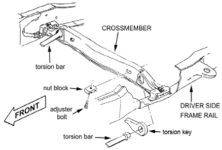
5. Locate the torsion bar crossmember. There is a bolt on each side of the crossmember that adjusts the torsion bar preload. Measure or mark the exposed length of the adjuster bolt for reference during re-assembly. (See Photo # 1)
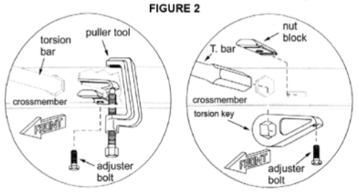
6. Position the appropriate torsion bar puller tool on the crossmember. Be sure the top of the puller tool engages the recess present in most crossmembers. Also be sure the lower end of the puller tool engages a recess on the torsion key near the adjuster bolt. (See Photo #2)
7. Using extreme caution, tighten the puller tool enough to take the load off the adjuster bolt. Remove the adjuster bolt & nut block, then unload the puller tool.
8. Note the orientation of the torsion bar key in relation to the end of the torsion bar. Slide the torsion bar forward, out of the torsion bar crossmember, & set the factory torsion bar key aside.
It ts not necessary to remove the torsion bars from the vehicle. Note: The torsion key should slide easily off the end of the torsion bar. However, depending on the age & use of the vehicle, rust & road debris may prevent easy removal. The installer can use a variety of methods to separate the torsion key if it is “stuck”, but using heat is not recommended.
9. Place the Skyjacker Suspension torsion key in the torsion bar crossmember, matching the same orientation as the original key. Slide the torsion bar back through the crossmember & into the torsion key. (See Photo #2)
10. Using the same precautions & procedures that were used during removal, load the torsion bar enough to install the nut block using the appropriate puller tool. Place the nut block back in the crossmember & start the adjuster bolt. Tighten the adjuster bolt to the same exposed length noted during disassembly. Unload the removal tool.
11. Lower the vehicle to the floor, manually bounce the front of the vehicle several times enough to settle the suspension.
12. Measure the ride height on each side. To raise the height, tighten the torsion bar adjuster bolt (with vehicle off the ground), to lower ride height, lessen the adjuster bolt. The torsion key is capable of increasing the ride height 1” ( Mid-Size) to 2” ( Full-Size) over factory specifications.
Do not increase ride above the specifications or premature ball joint failure will result.
