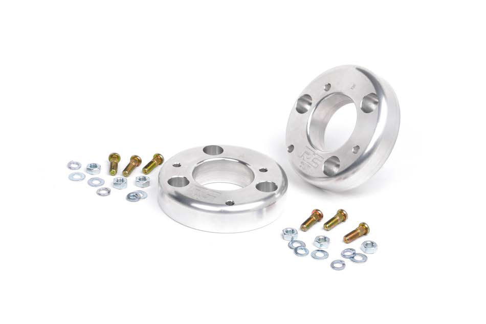
Rough Country 2 in. Leveling Lift Kit w/ Shocks (15-16 All)
Installation Time
3 hours
Tools Required
- 15mm Wrench
- 15mm Socket
- 29mm Socket
- 1 1/16” Wrench
- 21mm Wrench
- 16 mm Wrench
- 21 mm Wrench
- 3/8” mm Wrench
- 9/16” Wrench
- 9/16” Socket
- Hammer
- Floor Jack
- Jack Stands
- 18mm Socket
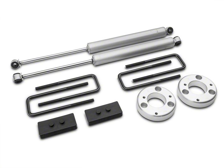
Shop Parts in this Guide
Jack up the front of the vehicle and support the vehicle with jack stands, so that the front wheels are off the ground. Next remove the front tires/wheels, using a 21mm deep well socket.
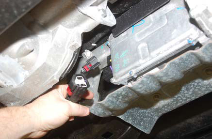
2. Using a 15mm socket remove the front skid if the truck is equipped with a full front skid. 3. Remove the EPAS (Electronic Power Assist Steering) Plugs as shown located on the steering assembly by the front differential. See Photo 1 & 2. This must be done BEFORE installation is started.
Photo 1
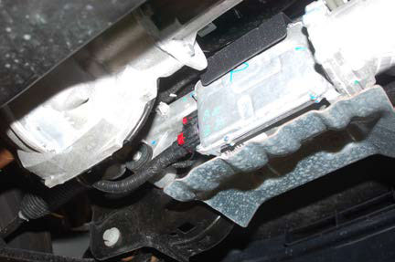
Photo 2
4. Using a 21mm wrench remove the nut from the tie rod on the knuckle. Using the appropriate tool, remove the tie rod from the knuckle. Push linkage forward to make room for installation. Retain factory hardware. See Photo 3.
5. Using a 8mm socket remove the ABS bracket from the knuckle and also remove the brake line bracket with a 10mm socket. See Photo 4.
Photo 3
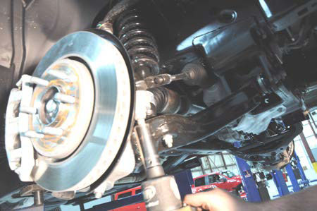
Photo 4
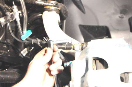
6. Next remove the caliper bolts with a 18mm socket as shown in Photo 5 and the dust shield bolts with a 8mm socket. Remove the ABS wire from the knuckle with a 5mm allen wrench.
7. Use a pair of plyers to pull off the axle dust cap and remove the axle nut with a 15mm socket. See Photo 6.
8. Remove the sway bar nut using a 18mm wrench. Retain factory hardware.
Photo 5
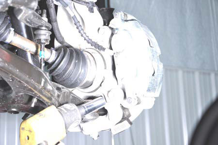
Photo 6
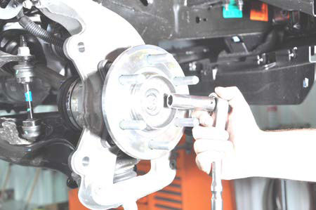
9. Using a 21mm wrench and a 1 1/16” socket loosen the lower control arm bolts. Do not remove the bolts just loosen them so you can later swing the lower control arm down. INSTALLATION INSTRUCTIONS Photo 3 Photo 4 Photo 5 Photo 6 Photo 1 Photo 2
10. Place jack stand under the knuckle for support. Remove upper control arm nut, using a 18mm wrench. Using the appropriate tool remove the ball joint to separate from the upper control arm. Do not allow the knuckle to pull out far enough that it pulls the shaft out of the differential. **Note** Use caution when removing the CV axle from the knuckle. Damage to CV actuator seal will affect 4wd operation. See Photo 7.
11. Use a 18mm socket to remove the lower strut nuts from the bottom of the control arm. See Photo 8. Retain factory hardware.
Photo 7
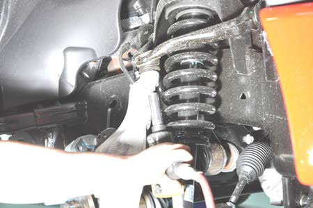
Photo 8
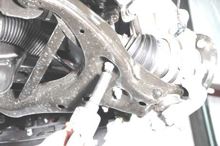
12. Using a 18mm wrench, remove the nuts on the upper strut tower that holds the assembly in place. See Photo 9.
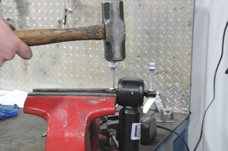
13. Lower the jack to let the lower control arm and knuckle swing down so the strut can be removed. Place the bar pin of the lower strut mount into a vise and hand start the nuts. Next use a hammer and knock the studs out of the bar pin. Retain factory hardware for reuse. See Photo 10.
Photo 9
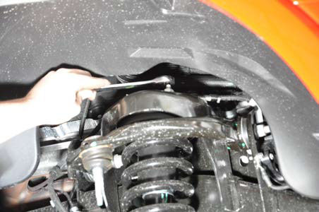
Photo 10
13. We recommend using OE instructions for disassembly and assembly of IWE actuator, the following instructions are for reference only.
14. Disconnect vacuum tubes from the actuator. See Photo 11.
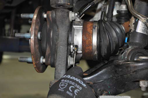
15. Using a 8mm wrench, remove the (3) bolts securing the actuator to the knuckle. See Photo 12. 16. Push CV axle inward allowing the knuckle to pivot outward to allow for more clearance to remove the strut.
Photo 11
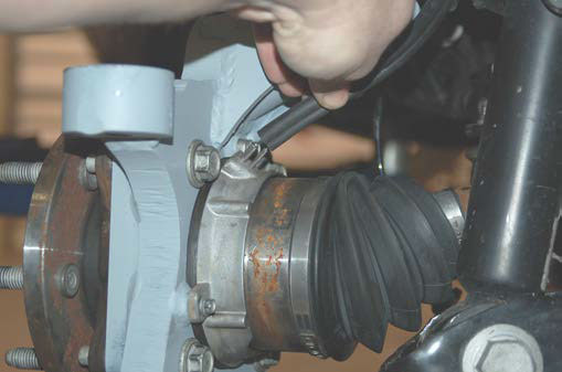
Photo 12
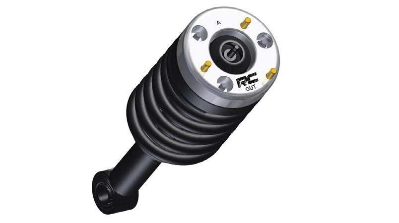
17. Looking at the strut spacer make sure you have two A spacers as shown below in the cad drawing. Insert the stud through the back side of the spacer. Use washers and nut to pull the stud into place.
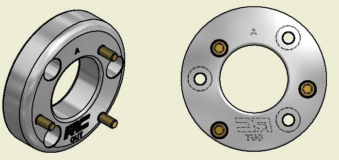
2014-15 F-150 Strut Spacers Insert studs into both A spacers
18. Install the new strut spacer on the strut, 2014 will use stock hardware and 9/16” socket and 2015 will use supplied 10mm nuts and 17mm socket from 569bag1. Torque to 30 ft/lbs. See Photo 13.
19. Install the A spacer on the strut with the supplied 10mm lock nuts, make sure you have the RC logo to the outside. See Photo 13. Tighten with a 17mm wrench.
Photo 13
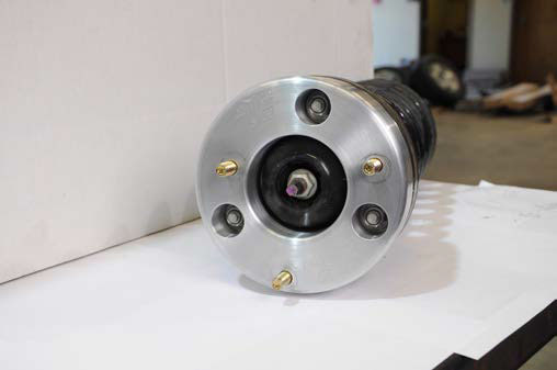
Photo 14
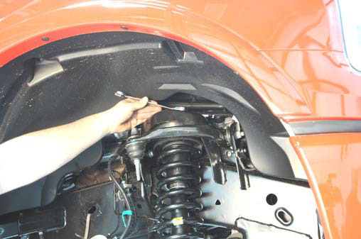
20. Install the factory studs back into the barpin on the lower mount of the strut. It may be necessary to hit the top of the strut with a hammer to seat the splines before tightening the factory nuts with a 18mm. See Photo 15.
Photo 15
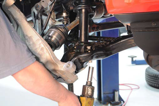
21. Make sure the actuator splines line up to the splines on the CV shaft. See photo 16. 22. Install CV shaft into the knuckle assembly. See Photo 17.
Photo 16
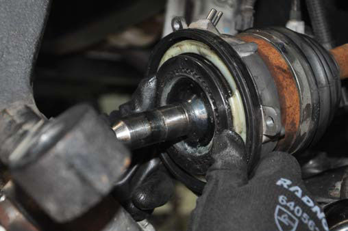
Photo 17
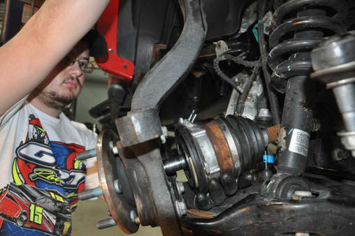
23. Using a floor jack, raise the lower control arm and connect the upper ball joint on the upper control arm to the spindle. Using a 21mm wrench, torque to manufacturer specs. If ball joint turns while tightening, use a 3/8” wrench to hold the ball joint.
24. Reinstall the steering linkage nut using a 21mm wrench.
25. Using a hand vacuum pump, apply and hold 24inHG of vacuum to the actuator through the large port. See Photos 18 and 19.
Photo 18
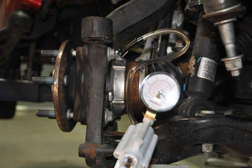
Photo 19
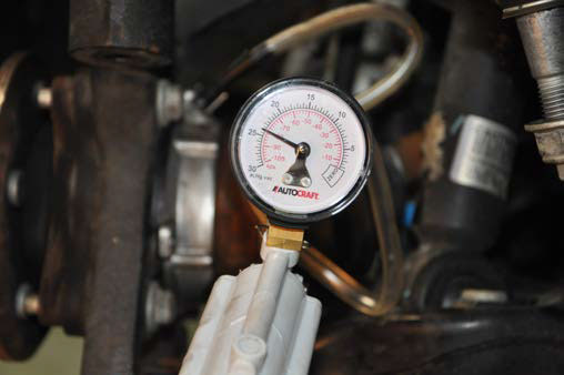
26. Install the (3) bolts securing the actuator to the knuckle and tighten using an 8mm wrench. See Photo 20.
27. With vacuum still applied to actuator. Measure the depth of the CV shaft treads protruding through the hub bearing. If minimum 15.5mm or .61” is not achieved, rotate the hub to eliminate binding of the splines. See Photo 21.
Photo 20
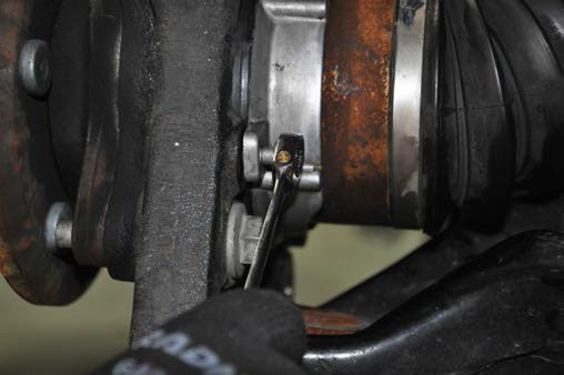
Photo 21
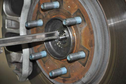
28. Install axle nut and tighten to 30 lb.ft. Do Not Use and impact, caution must be taken or damage to shaft may occur.
29. Verify free rotation of the hub with NO CV shaft rotation. No clicking or grinding noise should be present
30. Release the vacuum from the actuator and rotate the hub to engage the actuator. You may hear/feel the actuator engage.
31. Verify that the hub and CV rotate together. Reconnect the vacuum lines to the actuator.
32. Next slide on the brake rotor and install the brake caliper with the factory hardware and a 18mm socket.
33. Install the ABS line to the knuckle.
34. Repeat steps 4-33 on opposite side of vehicle.
35. Using a 18mm wrench, reinstall sway bar using factory hardware. Torque to factory specs.
36. Install the wheels / tires, using a 21mm deep well socket.
37. Reconnect the EPAS plugs.
38. Jack up the vehicle and remove the jack stands. Lower the vehicle to the floor and torque all bolts to factory specifications.
39. Vehicle will have to have a front-end alignment.
40. If the rear block kit & shocks was ordered with the kit please proceed to the next section. REAR INSTALLATION INSTRUCTIONS 1. Chock the front wheels. 2. Jack up the rear of the vehicle and place jack stands underneath the frame rail. Lower the 3. Remove the tires and wheels. 4. Remove rear shocks using a 15mm, and 18mm wrench. Save the stock hardware it will be used later. 5. Place the floor jack underneath the axle and remove the stock u-bolts. Lower the axle down to allow the blocks to be installed in between the stock block and the spring perch. Install the new u-bolts and secure with fasteners provided. 6. Assemble the rear shocks 658694, and install in the stock position with stock hardware, using a 15mm and 18mm wrench. Note: N2.0 shock absorbers are designed to run with the body of the shock absorber on the axle mount and the piston rod on the frame end.
POST INSTALLATION INSTRUCTIONS
1. Check all fasteners for proper torque. Check to ensure there is adequate clearance between all rotating, mobile, fixed and heated members. Check steering for interference and proper working order. Test brake system.
2. Perform steering sweep. The distance between the tire sidewall and the brake hose must be checked closely. Cycle the steering from full turn to full turn to check for clearance. Failure to perform inspections may result in component failure.
3. Re torque all fasteners after 500 miles. Visually inspect components and re torque fasteners during routine vehicle service.
4. Readjust headlights to proper settings.
MAINTENANCE INFORMATION
It is the ultimate buyers responsibility to have all bolts/nuts checked for tightness after the first 500 miles and then every 1000 miles. Wheel alignment steering system, suspension and driveline systems must be inspected by a qualified professional mechanic at least every 3000 miles
