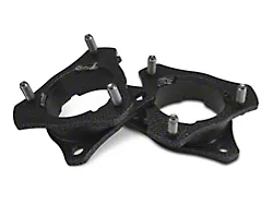
How to Install Raptor Series 5 in. Magnum Straight Oval Side Step Bars - Black - Rocker Panel Mount on your Silverado
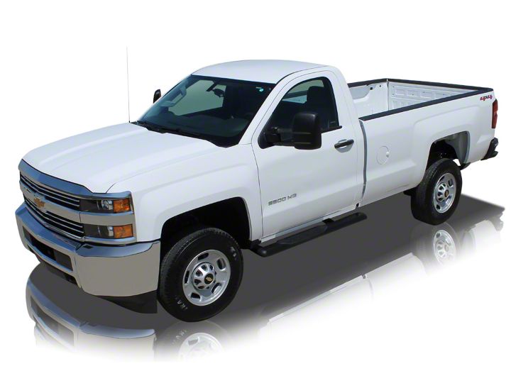
Shop Parts in this Guide
Torque Specifications:
For Rocker Panel Mount Installations
M8 through M12 bolts and nuts are set to 15-20 ft lbs.
Note: When installing the brackets and bars, all hardware must be left loose until all the items are attached.
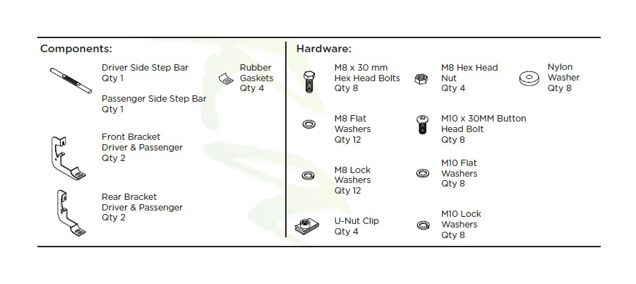
1. Remove all contents from the package and check stainless steel tubes for any damage. Also, verify that all components and hardware listed above are included before you begin installation.
2. Read installation manual and installation drawing completely. Understand all brackets and bolts before installation.
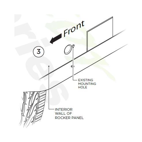
3. Existing mounting holes are located on the interior wall of the rocker panel. These mounting holes will be used per the following instruction.
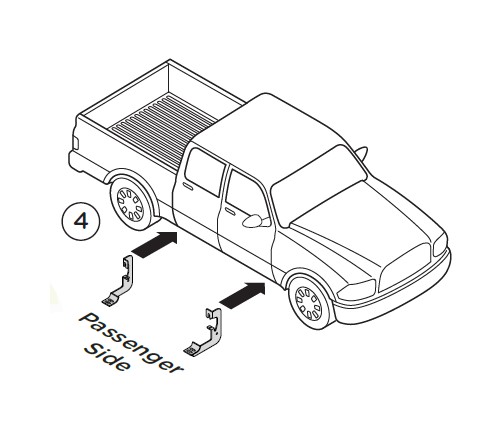
4. On passenger side of vehicle, align Front and Rear Brackets as shown.
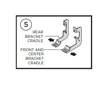
5. Front Bracket Cradle faces to the rear of truck and Rear Bracket Cradle faces to the front of truck.
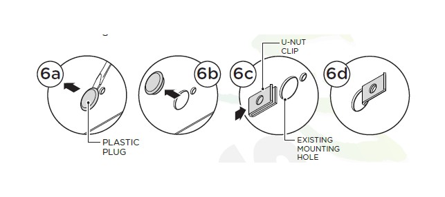
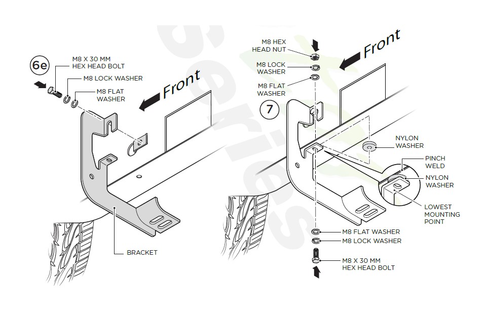
6. If specified holes in the wall of the rocker panel are not threaded, remove plastic plug (6a and 6b) and insert U-Nut Clip so that the threads are facing away from you (6c and 6d). Fasten using one (1) M8 x 30 mm Hex Head Bolt, one (1) M8 Flat Washer and one (1) M8 Lock Washer.
7. Complete installation of brackets by placing one (1) Nylon Washer between lower mounting point and pinch weld. Then fasten using one (1) M8 x 30 mm Hex Head Bolt, two (2) M8 Flat Washers, two (2) M8 Lock Washers and one (1) M8 Hex Head Nut. Repeat this procedure for remaining brackets.
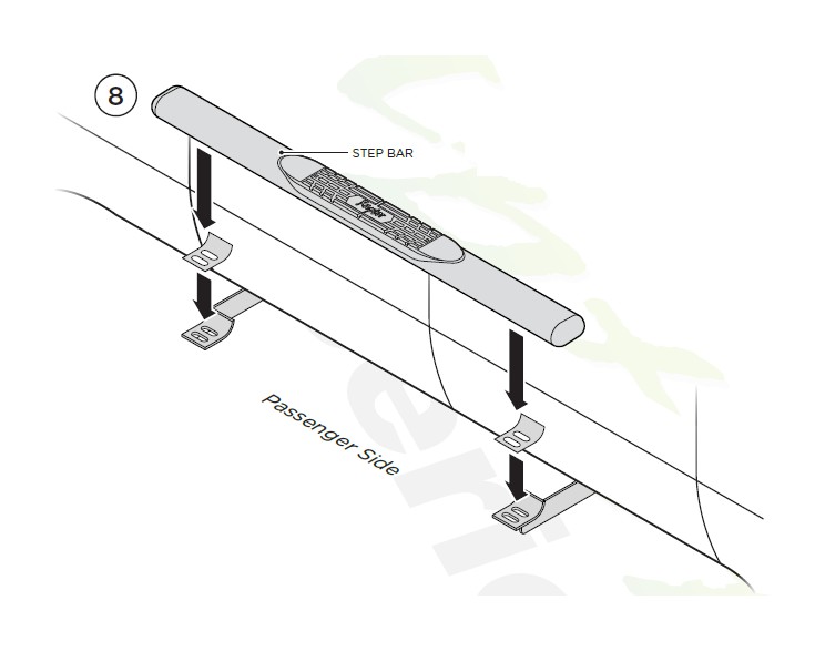
8. Place Step Bar and three (3) Rubber Gaskets onto Brackets. Each Step Bar is marked Driver and Passenger.
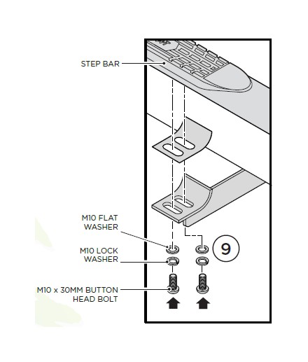
9. Install Step Bar and Rubber Gasket onto each Bracket and attach using two (2) M10 Button Head Bolts, two (2) M10 Lock Washers and two (2) M10 Flat Washers per bracket.
Tighten until the split lock washer is flat against bracket and snug. DO NOT over tighten and strip the threaded insert in the tube.
Repeat these steps for driver side installation. When all hard-ware is in place, everything must be tightened. See Page 1 for Torque Specifications.
