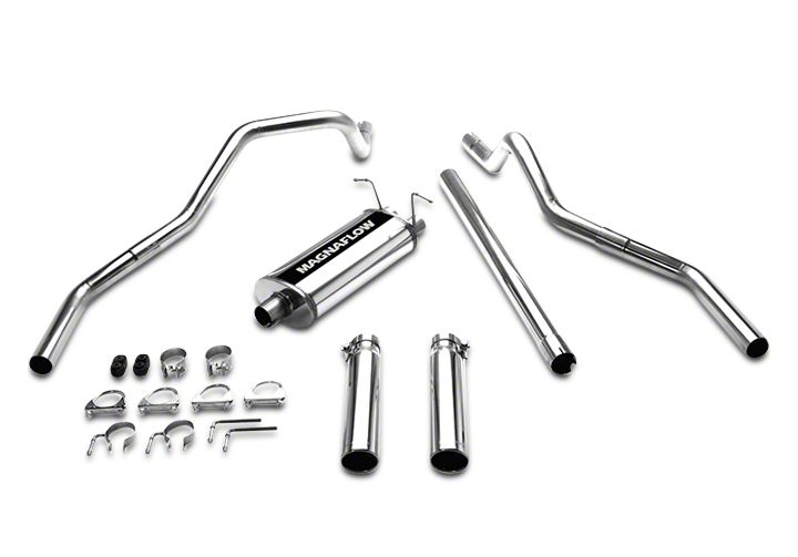
How to Install Magnaflow MF Series Cat-Back Exhaust - Split Rear Exit on your F-150

Shop Parts in this Guide
1997-2003 FORD F-150 4.6L/5.4L V8 EC/SB DUAL REAR EXIT
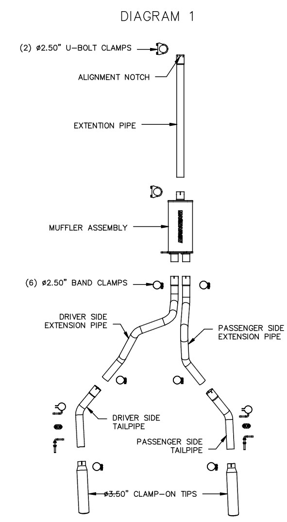
DIAGRAM 1

Warning: When working on, under, or around aryweyilcle exercise caution. Please allow the vehicle's exhaust system to cool before removal, as exhaust system tempera:was may cause severs bums rworldng without a lift, always consult vehicle manual for comma Nang specifications. Always War steely glasses and maw a agile work area. Serious Imlay or death could occur ffsgfety memos, are not followed
Nmv MIGNAFZOW Perfemnance dual mit tnalcsysteim ante designed toilt stock.height vehicles with OEM hitches and spare wheel and are combos. Vehicles with qftermarbst amwonents such as trailer hitches, larger spare wheel and tire, or ride height changes may mare modification ofthe exhaust systemfora
ProPer.fit =OVA
Step 1: (Carefully read all instructions before installation) To remove the OEM exhaust system, you will need to cut the front of the tailpipe about 1" behind the muffler. Once this is done, the tailpipe can be removed from the OEM rubber insulators and extracted from the vehicle. Do not damage the OEM rubber insulators, as they will be re-used to mount the now exhaust system. Unbolt the clamp attaching the front muffler extension to the catalytic converter =tension, and remove the assembly from the OEM rubber insulators.
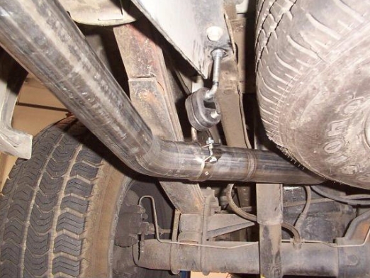
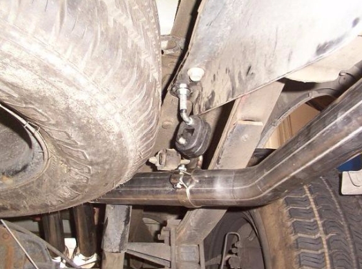
Step 2: Begin installation by bolting the new extension pipe to the catalytic converter extension using the supplied 2.50" clamp. Be sure to line up the notch at the front of the extension pipe with the peg on the catalytic converter extension. Leave all fasteners loose for final adjustment. Working rearward, install the muffler, extension pipes, and tailpipes using the supplied hardware as shown in the system diagram. A hanger bracket and mounting fasteners are supplied to hang the tailpipes from a pre-drilled hole in the frame as shown in Diagram 2 and 3. (The photo of the hanger assembly my differ slightly for your vehicle, it is provided for reference). You can now adjust the height of the tailpipes by adjusting the threaded hangers. Adjustable tip assemblies are provided to fit a variety of aftermarket bumpers and rollpans. Once a final position is chosen for the tips, it is recommended to have them welded to the tailpipes.
Warning: When working on, under, or around an ;twisted e midge caution. Please allow the vehicle's exhaust system to cool before removal, as exhaust system tempera:was may cause seven' burns If wore without a lift, always consult vehicle manual for coned lifting specifications. Always War steely gksses and maw a stifs work area. Serious filmy or death could occur ffseety memos, are not followed
Note: MIGNAFZOW Perfimnance dual salt tnalcsystems are designed to fit atm:la:eight vehicles with OEM hitches and spare wheel and tire combos. Vehicles with qftermarbst ootswonents such as trailer hitches, larger spare wheel and We, or ride height changes may require modification of the exhaust system* a
1h =1
Step 3: With all components mounted loosely, adjust the system for overall aesthetics and clearance of frame & bodywork. (MAGNAFLOW recommends at least 1/2" of clearance between the exhaust system and any body panels to prevent heat-related body damage or fire.)

Step 4: Once a final position has been chosen for the new system, (nerdy tighten all fasteners from front to rear. The supplied band clamps must be VERY tight to properly align the pipes and prevent leaks (Approximately 40ft-lbs). U-bolt clamps should be tightened to approximately 30-35ft-lbs. Inspect all fasteners after 25-50 miles of operation and =tighten if necessary.


