FREE 1 to 3-Day Delivery on Orders $119+ Details
How to Install Firestone Standard Duty Air Command Single-Path Air Control System - Analog Gauge
Tools Required
- 3/16" DRILL BIT
- (2) 7/16” WRENCHES OR SOCKETS
- 9/16” WRENCH OR SOCKET
- WIRE CRIMPER/STRIPPER
- PHILLIPS SCREW DRIVER
- POWER DRILL
- ELECTRICAL TAPE
- PLIERS
- UTILITY KNIFE
- CENTER PUNCH OR MARKING TOOL
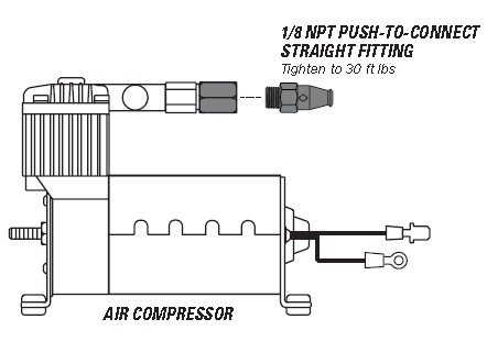
1. PREPARE THE AIR COMPRESSOR
1. Install 1/8 NPT Push-to-Connect Straight Fitting to the head of the Air Compressor.
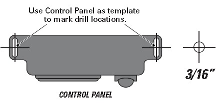
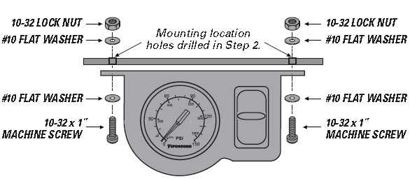
2. DRILL HOLES FOR CONTROL PANEL INSTALLATION
Use the location you selected during the Planning the Installation step on Page 4.
1. Using the Control Panel slots as a template, mark two drill locations with a punch or marking tool.
2. Drill a 3/16" diameter hole on each center mark.
3. Do not mount the Control Panel until Step 8.
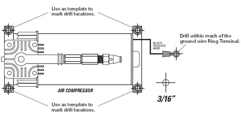
3. DRILL HOLES FOR AIR COMPRESSOR INSTALLATION
IF YOU ARE USING THE OPTIONAL FIRESTONE AIR COMPRESSOR MOUNTING KIT (PART # 2497), SKIP THIS STEP AND REFER TO THE MOUNTING KIT’S INSTRUCTIONS.
CHECK SURROUNDING AREA AND BACK SIDE OF MOUNTING LOCATION TO AVOID DRILLING INTO EXISTING LINES OR WIRING.
1 Using the Air Compressor as a template, mark four drill locations with a punch or marking tool.
2 Drill ground wire fastening location within reach of the ground wire Ring Terminal.
3 Remove any burrs and debris from drill holes.
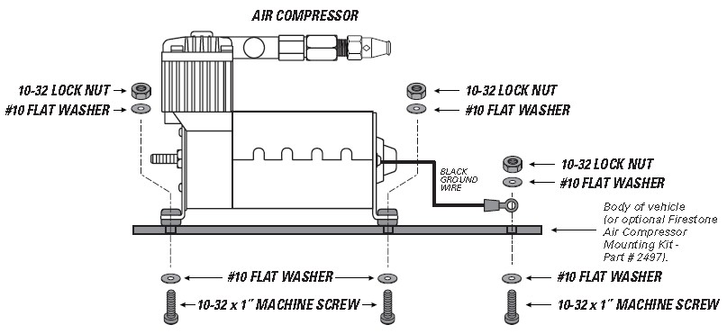
4. INSTALL AIR COMPRESSOR
DO NOT OVER TIGHTEN MOUNTING BOLTS AND NUTS. TOO MUCH TORQUE CAN CRUSH THE BRASS INSERT AND RUBBER ISOLATORS.
1. Mount the Air Compressor to the drill hole location using the supplied fasteners. DO NOT OVER TIGHTEN.
2. Mount the black ground wire using the supplied fasteners. Assure that the Ring Terminal makes a solid contact with bare metal for a proper ground. (Optionally, you can run the negative to the negative battery terminal.)
TO CREATE A PROPER GROUND, ASSURE THE GROUND RING TERMINAL CONTACTS BARE METAL AND IS FASTENED SECURELY. AFTER INSTALLATION, YOU MAY OPTIONALLY COAT THE RING TERMINAL IN SILICONE TO PROTECT IT FROM CORRODING.
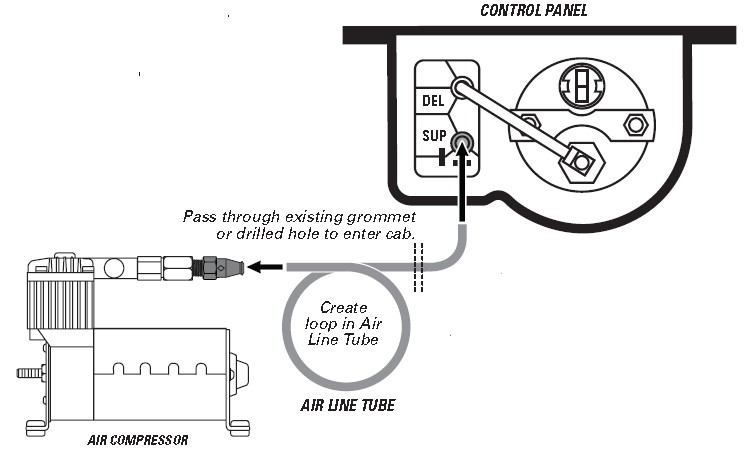
5. ROUTE AIR LINE TUBE FROM AIR COMPRESSOR TO CONTROL PANEL
Use the route you selected during the Planning the Installation step on Page 4.
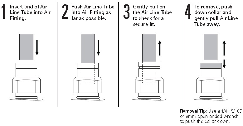
EXHAUST ALL AIR FROM THE SYSTEM PRIOR TO RELEASING AIR TUBES FROM AIR FITTINGS.
FOR PROPER INSTALLATION, SOAK AIR LINE TUBE ENDS IN HOT WATER BEFORE INSTALLING ONTO BARBED FITTINGS.
1. Route the Air Line Tube from the Air Compressor to the Control Panel, leaving room to secure line safely. Use guidelines below to cut.
2. Install the Air Line Tube end onto the barbed fitting on the back of the Control Panel switch as shown.
3. Install the Air Line Tube end into the 1/8 NPT Push-to- Connect Straight Fitting on the top of the Air Compressor.
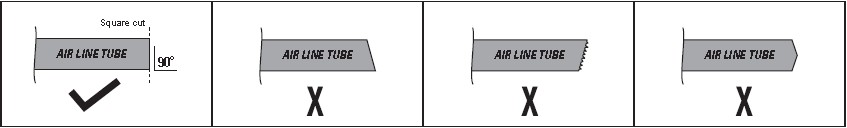
DO Make sure the cut is as square as possible. Use a tube cutter or sharp utility knife.
DON’T Fold or kink the Air Line Tube. Cut the Air Line Tube at an angle. Use pliers, scissors, snips, saws, or side cutters.
PROPER AND IMPROPER CUTS IN THE AIR LINE TUBE
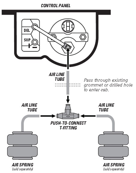
6. INSTALL T-FITTING AND ROUTE AIR LINE TUBE TO CONTROL PANEL
Use the route you selected during the Planning the Installation step on Page 4.
EXHAUST ALL AIR FROM THE SYSTEM PRIOR TO RELEASING AIR TUBES FROM AIR FITTINGS.
FOR PROPER INSTALLATION, SOAK AIR LINE TUBE ENDS IN HOT WATER BEFORE INSTALLING ONTO BARBED FITTINGS.
1. Route the Air Line Tube from the Control Panel to the Air Springs.
2. Install the Air Line Tube end onto the barbed fitting on the back of the Control Panel pressure gauge as shown.
3. Determine a safe location for the Push-to-Connect T-fitting, where Air Line Tubes from the Air Springs and the Control Panel can safely meet.
4. Install the Air Line Tubes from the Air Springs into opposite ends on the Pushto- Connect T-fitting as shown.
5. Install the Air Line Tube from the Control Panel to the single end on the Push-to- Connect T-fitting.
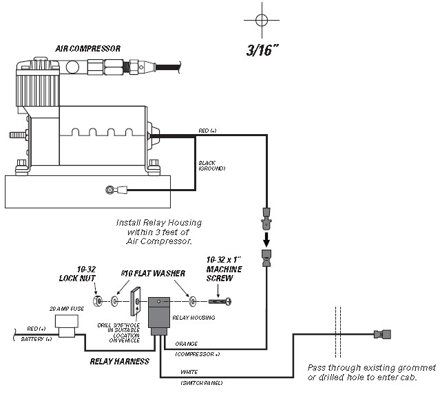
7. INSTALL RELAY HARNESS
1. Select a safe location within 3 feet of the Air Compressor.
2. Mark and drill a 3/16" hole to mount the relay housing on the Relay Harness. Secure with fasteners shown.
3. Route the white wire with the female spade connector labeled “switch panel” to the Control Panel.
8. FINISH WIRING AND INSTALLATION
1. Connect wires, install Ring Terminals and Wire Connectors as shown below.
2. Fasten Control Panel ground wires to vehicle as shown.
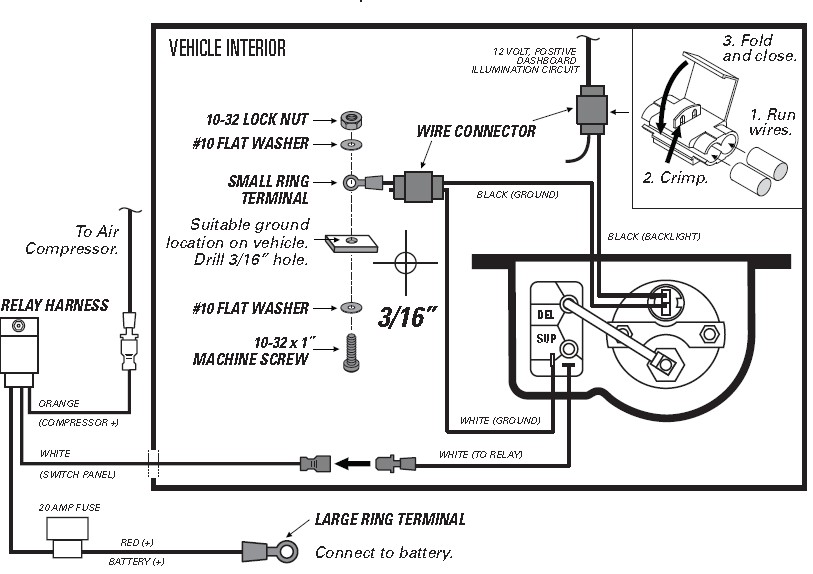
3 Install the Control Panel using the supplied fasteners.
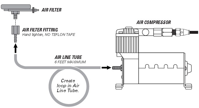
9. INSTALL THE AIR FILTER
FOR PROPER INSTALLATION, SOAK AIR LINE TUBE ENDS IN HOT WATER BEFORE INSTALLING ONTO BARBED FITTINGS.
1. Install the 1/4 NPT x 1/4" Tube Fitting onto the Air Filter Inlet as shown, hand tighten.
2. Use supplied Nylon Ties to secure the Air Filter to a dry, protected location no more than 6 feet from the Air Compressor.
3. Cut a length of Air Line Tube to run from the Air Compressor to the Air Filter. Attach the Air Line Tube to the barbed fittings as shown below.
THE AIR LOOP CREATES A TRAP FOR CONDENSATION TO GATHER. WITHOUT THIS TRAP, THE AIR COMPRESSOR COULD BE DAMAGED BY WATER INTAKE.
10. CLEAN UP INSTALLATION
1. Clean up the installation using supplied Nylon Ties, and return all factory parts and materials to operative state.
USING SUPPLIED NYLON TIES, SECURE ALL WIRING AND AIR LINE TUBE IN A MANNER THAT DOES NOT OBSTRUCT YOUR VIEW OR ABILITY TO SAFELY OPERATE THE VEHICLE.
10. TEST THE SYSTEM
With the Air Command Kit and your Air Springs installed, you are ready to test the system.
1 Re-attach the negative battery cable.
2. Turn on your vehicle’s ignition.

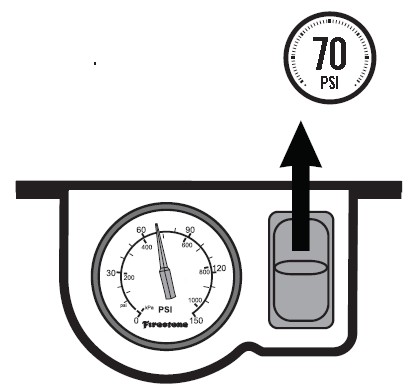
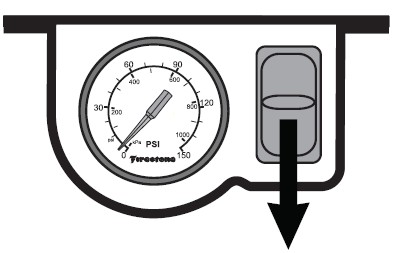
3. Push paddle switch up to inflate the Air Springs to 70 PSI.
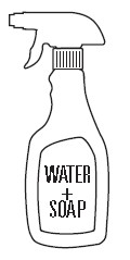
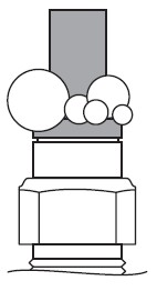
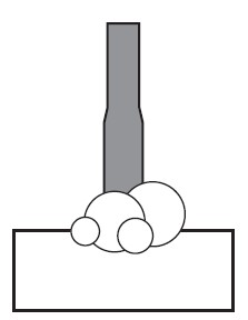
4. Spray fittings with soap and water mixture.
5. Observe bubbles.
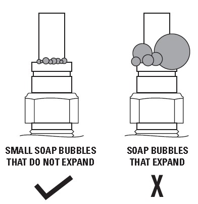
NO LEAKS? Congratulations! You’re riding right with the flip of a switch! Remember to Review the Operating Instructions.
LEAK? Bummer. Continue to Step 11 to fix the leak.
11. FIXING AN AIR LEAK
EXHAUST ALL AIR FROM THE SYSTEM PRIOR TO RELEASING AIR TUBES FROM AIR FITTINGS.
1. Push paddle switch down to release all air pressure from the Air Springs.
NOTE: While doing this, if you get a quick burst of air prior to the gauge dropping to 0 PSI, your lines are incorrectly swapped.
LEAK AT AIR LINE TUBE AND AIR FITTING
Release Air Line Tube (see page 4). Review proper cuts and procedures in Step 5. Repeat Step 6.
LEAK AT BASE OF AIR FITTING ON AIR SPRING
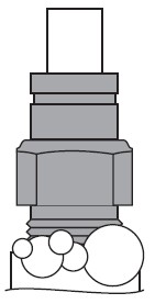
Tighten Air Fitting one turn or until leak stops.
LEAK AT A BARBED FITTING
Being careful not to scar the metal barbs, cut away, check for debris. Trim Air Tube Line, soak for 5 minutes in hot water. Reinstall.