Guaranteed Free Delivery by 12/24! available on most items - Details
How to Install Corsa 3 in. Sport Muffler Upgrade Kit (2017 Raptor) on your Ford F-150
Installation Time
1 hours
Tools Required
- 3/8” drive ratchet
- 3/8” drive 10mm socket
- 3/8” drive 15mm deep socket
- 10” 3/8” ratchet extension
- Grommet pullers
- Soap and water solution
- Torque Wrench
- Penetrating lubricant spray
- Safety glasses

Shop Parts in this Guide
Please take time to read and understand these installation instructions.
CORSA recommends that the installation of this system be performed by a qualified service center or professional muffler installer who has the necessary equipment, tools and experienced personnel. However, if you decide to perform this install, the use of a hoist and an additional person will be required.
CAUTION: Never work on a hot exhaust system. Allow time for the vehicle to cool. Always wear eye protection when working under a vehicle.
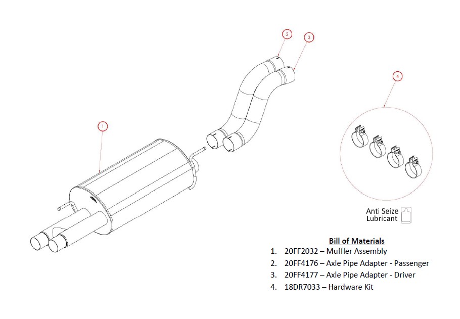
Please confirm that all parts are present according to the bill of materials before beginning the in
Factory Exhaust System Removal:
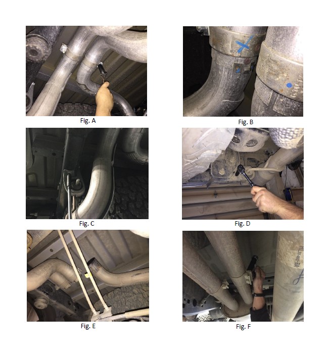
1. Using a 15mm deep socket and 3/8” drive ratchet, loosen the two clamps on the axle pipes located just over the rear axle downstream of the rear muffler. (Fig. A) Using a screw driver pry open the spring clip holding the locating pin on the driver and passenger side tailpipes. (Fig. B)
2. Using a 10mm socket, long extension and 3/8” drive ratchet, loosen and remove the driver and passenger side axle pipe hanger assemblies. (Fig. C)
3. Using a 10mm socket, 3/8” drive ratchet, and a long extension, loosen and remove the two nuts and studs holding the tailpipe hanger assembly located to the inside of the driver and passenger side exhaust tips. (Fig. D) The tailpipes will no longer be supported. Slightly lower the passenger side tailpipe assembly and remove rearwards. Next, slide the driver side tailpipe assembly rearwards to free it from the connection point and maneuver the tailpipe from over the axle and around the spare tire. (Fig. E) Leave the hanger grommet assemblies on the tailpipe hangers as the tailpipe assemblies will be reused in the installation portion of these instructions.
4. Loosen the clamp and sleeve clamp connection located after the stock resonator using a 15mm deep socket and ratchet. The stock clamp is welded to the resonator assembly and cannot be removed or rotated. (Fig. F)
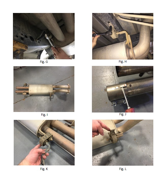
5. Using a 10mm socket and 3/8” drive ratchet loosen and remove the two bolts holding the front muffler hanger. (Fig. G) Next, loosen and remove the bolt holding up the rear muffler hanger assembly. (Fig. H) The rear muffler will no longer be supported; remove by sliding it rearwards to free the muffler inlet pipes from the connection point. (Fig. I)
6. Remove the stock sleeve clamp from the muffler inlet pipe by prying open the spring clip with a flat head screw driver and sliding the clamp off the pipe. (Fig. J) Place the stock sleeve clamp in a safe location as it will be reused during the installation of your new Corsa Performance Exhaust System.
7. Removal all of the hanger grommet assemblies from the stock rear muffler and store them in a safe location, as they will be reused during the installation of your Corsa Performance Exhaust System. (Fig. K & L)
NOTE: The use of a soap and water solution may aid in the removal of hanger grommets.
Factory Exhaust Removal Pictures
Installation of CORSA Exhaust System:
NOTE: Apply the anti-seize lubricant (supplied) to the threads ONLY of all the clamps and flange bolts. Failure to follow this procedure can cause nuts to seize on clamps and potentially destroy threads. After applying anti-seize lubricant, be sure to thoroughly clean your hands, as lubricant will tarnish stainless steel. All clamps should be tightened using a properly calibrated Torque Wrench. Using an air impact gun will damage the clamp and reduce its ability to effectively seal the joint. It may also cause the joint to separate, thereby causing damage to your exhaust system and to your vehicle.
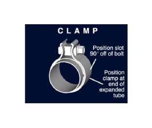
NOTE: Align all clamps so that the center of the clamp bolt is 90 degrees from the notch in the pipe. (See Fig. CLAMP)
NOTE: IN ORDER TO ACHIEVE AND CONFIRM PROPER CLEARANCES BETWEEN THE EXHAUST SYSTEM ROUTING AND THE REAR SUSPENSION, THIS KIT MUST BE INSTALLED ON A TWO POST LIFT OR WITH THE REAR SUSPENSION FULLY DECOMPRESSED.
1. Remove all exhaust components from the shipping carton, including all clamps and hardware.
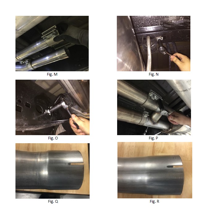
2. Locate the stock sleeve clamp removed from step #6 of the stock exhaust removal instructions. Install the sleeve clamp on the driver stock resonator or Corsa K-Pipe outlet pipe so that the bolts are vertical, with the nuts towards the ground and the bolts are towards the center of the vehicle. (Fig. M)
3. Locate the Corsa performance muffler and stock front muffler hanger and the rear muffler hanger grommet assembly removed during step #7 of the stock exhaust removal instructions. Install the stock front hanger assembly onto the Corsa muffler in the same orientation as it was on the stock muffler. Install the stock rear muffler hanger grommet assembly onto the rear hanger of the Corsa muffler in the same orientation as stock.
NOTE: The use of a soap and water solution may aid in the installation of hanger grommets.
4. Slide the passenger rear muffler inlet pipe into the expanded end of the resonator outlet pipe and the driver side into the sleeve clamp. Next, install the rear muffler hanger grommet assembly and bolt it down using a 10mm socket and 3/8’ drive ratchet. (Fig. N) Install the front muffler hanger to the vehicle frame using the 10mm socket and 3/8’ drive ratchet. (Fig. O) Snug the sleeve clamp using a 15mm deep socket and 3/8” drive ratchet followed by the clamp. (Fig. P)
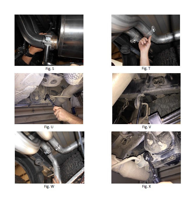
5. Locate the driver and passenger side axle pipe adapterS along with two 3” clamps for each axle pipe adapter. Identify the adapter inlet and outlet sides. The inlet side will have visible clamp marks/rings (Fig. Q) while the outlet end will have a smooth finish. (Fig. R.) Install the clamps on both ends of the adapters so that when the adapters are installed in the vehicle, the clamp bolts are perpendicular to the ground and the nuts are facing towards the ground. The Passenger side bolt clamp should be towards the passenger side of the vehicle and driver side bolt clamp should be on the driver side. Starting with the passenger side adapter, slide the expanded inlet end of adapter pipe over the passenger side muffler outlet pipe. Snug the clamp at the muffler connection point using a 15mm deep socket and ratchet. (Fig. S) Next, slide the expanded inlet end of the driver side adapter over the driver side muffler outlet pipe. Snug the clamp at the muffler connection point using the 15mm deep socket and ratchet. Leave the outlet clamps loose at the time.
6. Locate the stock driver side tailpipe assembly. Snake the assembly around the spare tire and over the rear differential and slide the tailpipe inlet end into the expanded outlet end of the driver side adapter. (Fig. T) Next, slide the rear tailpipe hanger grommet assembly against the vehicle frame, insert the threaded stud assembly from the rear of the vehicle and install the two nuts using a 10 mm socket and ratchet. (Fig. U) Bolt the front tailpipe hanger grommet assembly to the vehicle frame using the 10mm socket and ratchet. (Fig. V) Snug the 3” clamp installed in step #6 using a 15mm deep socket and ratchet.
NOTE: The rear tailpipe hanger has plenty of adjustment. Ideally the bottom lip of the hanger grommet should be parallel and level with the vehicle chassis. Loosening and adjusting the positon of the hanger grommet will result in lateral and vertical tip adjustment.
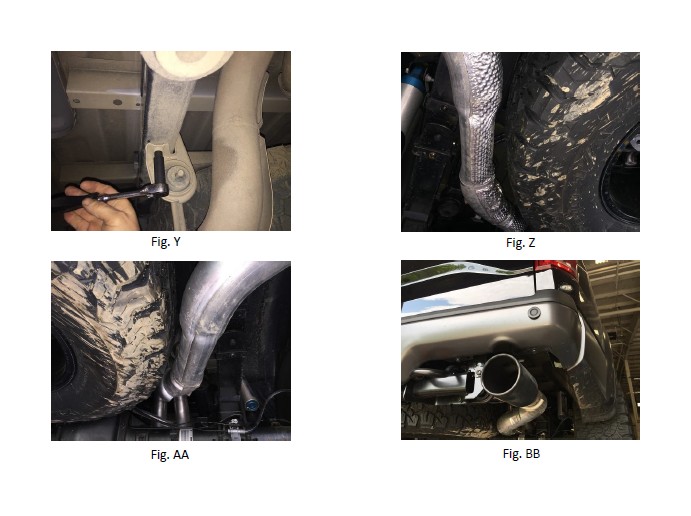
7. Locate the stock passenger side tailpipe assembly. Slide the inlet end of the tailpipe into the expanded passenger outlet. (Fig. W) Next, slide the rear tailpipe hanger grommet assembly against the vehicle frame, insert the threaded stud assembly from the rear of the vehicle and install the two nuts using a 10mm socket and 3/8” ratchet. (Fig. X) Bolt the front tailpipe hanger grommet assembly to the vehicle frame using a 10mm socket and ratchet. (Fig. Y) Snug the 3” clamp installed in step #5 using a 15mm deep socket and ratchet.
NOTE: The rear tailpipe hanger has plenty of adjustment. Ideally the bottom lip of the hanger grommet should be parallel and level with the vehicle chassis. Loosening and adjusting the positon of the hanger grommet will result in lateral and vertical tip adjustment.
8. Visually inspect the exhaust system position, tip alignment, clamp orientation and position, and exhaust pipe clearance. Make any necessary adjustments at the slip joints. Check clearances between the spare tire and rear leaf spring suspension on both driver and passenger sides. (Fig. Z, AA, BB)
9. Starting at the front of the vehicle and working towards the rear, torque all the clamps to 45 ft-lbs.
10. It is STRONGLY SUGGESTED that all clamps be checked and re-tightened (if necessary) to the recommended torque after initial road testing of the vehicle, as thermal cycling has occurred on the system. Please wait until the system has fully cooled to perform this step.
NOTE: During cold weather start-ups, you may experience an exhaust sound that is deeper and louder in tone than usual. This is temporary and will diminish to normal levels once your engine has reached its normal operating temperature.
NOTE: Immediately following the installation of your exhaust system, you may experience a trace of smoke after initial start-up. DO NOT be alarmed. The smoke is caused by the burning of a small amount of forming oil residue used in the manufacturing process.
CORSA Exhaust Installation Pictures
