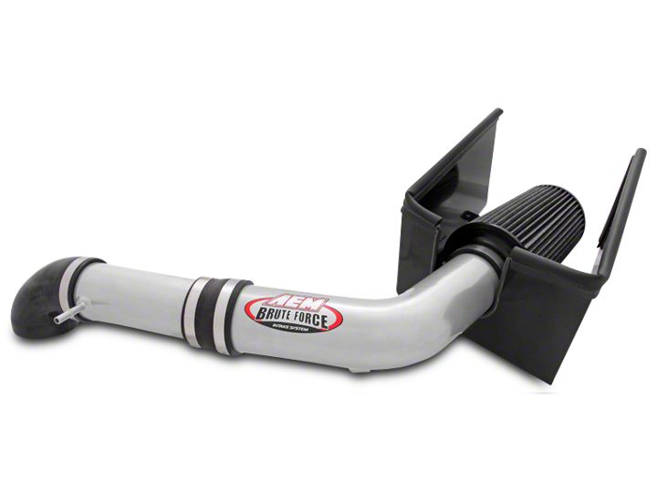
How to Install AEM Brute Force Cold Air Intake - Gunmetal Gray on your F-150
Shop Parts in this Guide
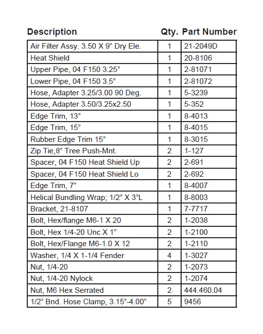
PARTS LIST:
Read and understand these instructions BEFORE attempting to install this product.
Failure to follow installation instructions and not using the provided hardware may
damage the intake tube, throttle body and engine.
1. Preparing Vehicle
a. Make sure vehicle is parked on level surface.
b. Set parking brake.
c. If engine has run in the past two hours, let it cool down.
d. Disconnect both battery terminals.
e. Do not discard stock components after removal of the factory system.
2. Removal of stock system
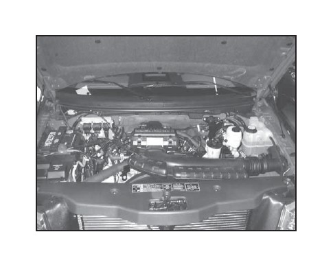
a. The engine bay with the factory air bix installed.
b. There is a section of the stock air system that is connected at the inner fender. Gently pull the inlet pipe towards the engine to loosen.
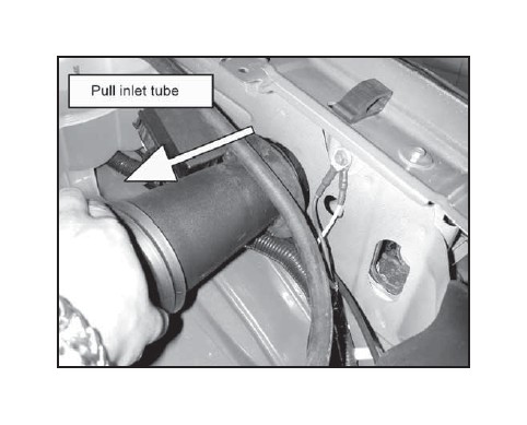
c. Loosen and remove bolt.
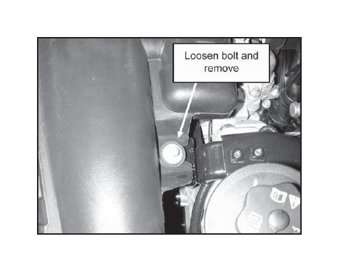
d. Locate the formed crankcase breather hose. Disconnect the upper adapter before the throttle body. Be careful not to damage the hose.
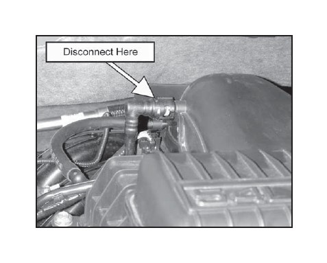
e. Disconnect the other end of the breather hose. This hose will be reused.
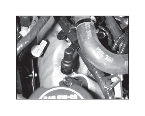
f. Remove the MAF Sensor connector. To do so, pull out the red tab and remove sensor.
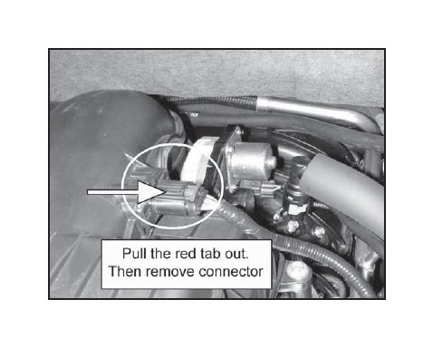
g. Loosen and remove the bolts on the right side of the air box just before the throttle body.
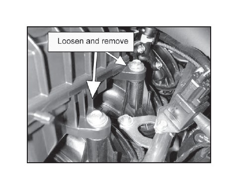
h. Remove the clip from the left side of the air box. The clip remains on the wire harness.
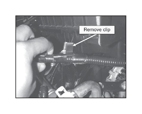
i. Loosen and remove the two remaining bolts. Remove the stock air inlet assembly.
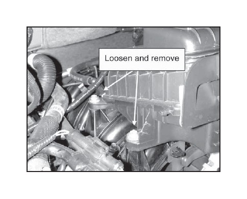
j. Remove the two TORX screws to the MAF sensor. Be careful not to damage sensor when removing.
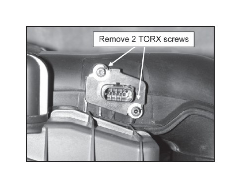
3. Installation of AEM® intake system.
a. When installing the intake system, do not completely tighten the hose clamps or mounting hardware until instructed to do so.
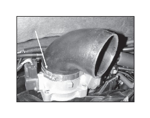
b. Attach provided coupler and hose clamp to the throttle body. The 3.5” opening should be on the throttle body. The 3.25” opening should be at the 4 o’clock position.
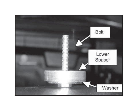
c. We will be installing the heat shield next. Assemble the following bolt, washer and lower spacer.
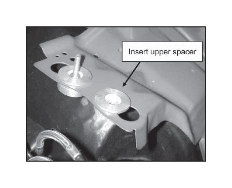
d. On the left is a fully assembled anchor for the heat shield. On the right, insert the upper spacer. The platform is located on the just behind the driver’s side headlight.
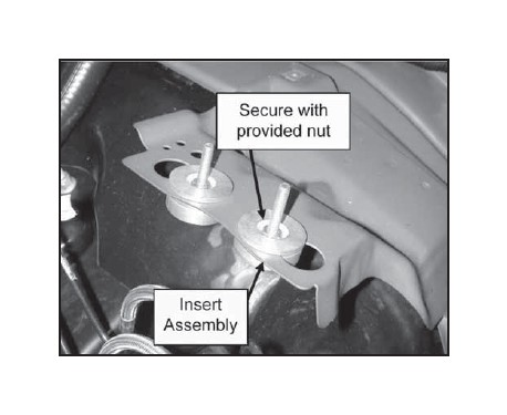
e. Insert the assembly from Step 3c into the upper spacer from underneath. Secure with provided nut.
f. Insert heat shield. Make sure the holes fit without stressing the anchor bolts. You may need to readjust for best fit. Secure third tab with provided bolt.
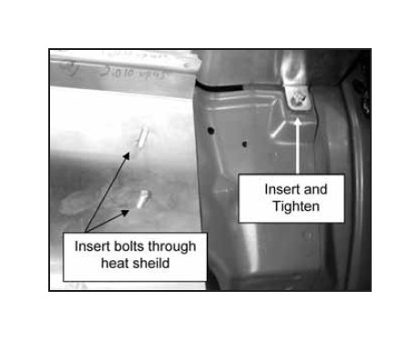
g. Secure the heat shield with the provided washers and nyloc nuts.
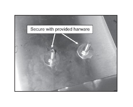
h. Attach rubber foam gasket material to the top of the heat shield and also to the front leg. Attach the rubber edge trim to the intake opening.
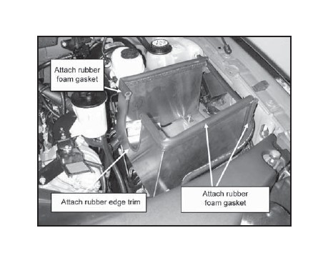
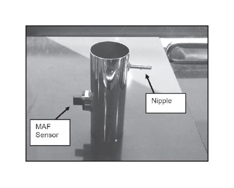
i. Insert the MAF sensor. The airflow direction should be pointing towards the nipple on the pipe. Secure the sensor with the provided washers and bolts.
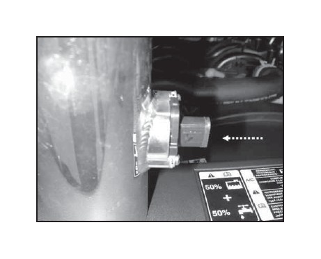
j. The upper inlet pipe should look like this.
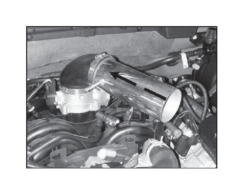
k. Insert the upper inlet pipe. Secure with provided hose clamp. Reconnect crankcase breather hose.
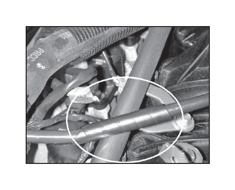
l. Wrap the hard plastic breather hose with the provided heli-tube. This will protect against wear on the fuel rail. The breather hose connects the crankcase to the intake system.
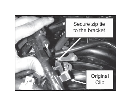
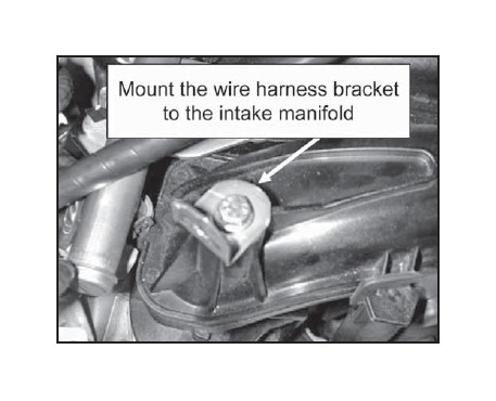
m. Secure the wire harness bracket to the intake manifold in part 1. Then secure the wire harness with provided zip tie to the wire harness bracket. The zip tie should be secured to the left side of the original clip. Cut away the excess zip tie. The wire harness should clear the breather tube.
n. On the stock system the breather crankcase hose sits in this orientation. We will need to rotate the head 45 degrees to mate to the nipple.
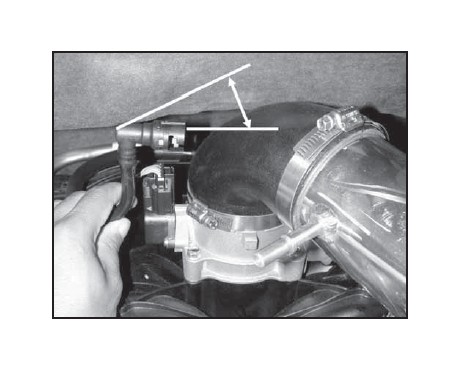
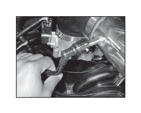
o. Once the head is rotated, then secure to the nipple.
p. Attach the reducer coupler and secure with the provided hose clamps. Do not fully tighten.
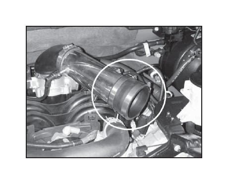
q. Insert the lower pipe as shown. The bracket should be pointing to the driver’s side.
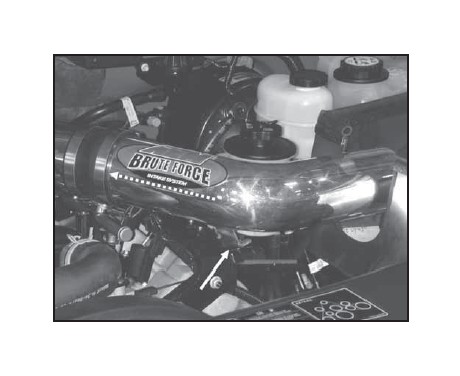
r. Align the bracket with the stock bolt and bolt location. Make sure both pipes are straight and there is clearance at the heat shield for the filter element.
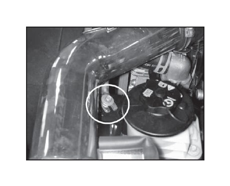
s. Reconnect the MAF Sensor harness and secure tab.
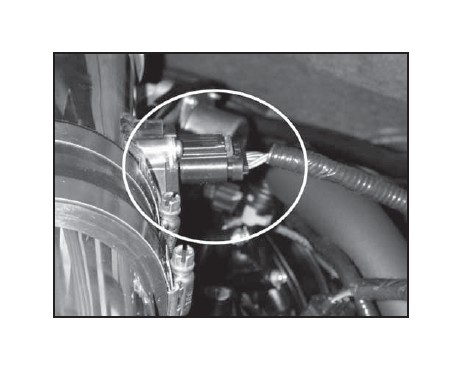
t. Attach the filter element and secure.
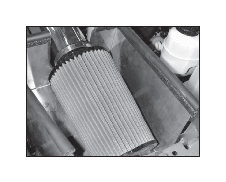
AEM® intake system installed
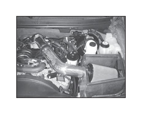
4. Reassemble Vehicle
a. Position the inlet pipes for the best fitment. Be sure that the pipes or any other components do not contact any part of the vehicle. Tighten the rubber mount, all bolts, and hose clamps.
b. Check for proper hood clearance. Re-adjust pipes if necessary and re-tighten them.
c. Inspect the engine bay for any loose tools and check that all fasteners that were moved or removed are properly tightened.
d. Reconnect battery terminals and start engine. Let the vehicle idle for 3 minutes. Perform a final inspection before driving the vehicle.
5. CARB Sticker Placement
a. The C.A.R.B. exemption sticker, (attached), must be visible under the hood so that an emissions inspector can see it when the vehicle is required to be tested for emissions. California requires testing every two years, other states may vary.
6. Service and Maintenance
a. It is recommended that you service your AEM® Dryflow™ filter every 20,000 miles for optimum performance. Use AEM Dryflow cleaning kit part # 21-110.
b. Use aluminum polish to clean your polished AEM® intake tube.
c. Use window cleaner to clean your powder coated AEM® intake tube. (NOTE: DO NOT USE aluminum polish on powder coated AEM intake tubes).
